Accessories 2 - 17
Four Slot Battery Charger Installation
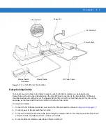
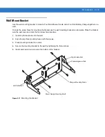
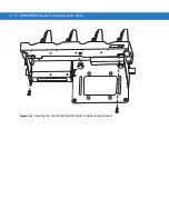
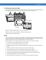
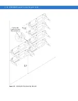
The Four Slot Spare Battery Charger has four mounting slots on the back. Around the slots are guides that assist in
proper alignment of the charger onto the mounting bracket. Gravity holds the charger in place.
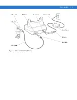
Figure 2-15
Installing the Battery Charger onto the Mounting Bracket
Position the charger over the mounting studs and slide the charger into place.
Ensure that the charger is seated properly.
Wiring
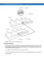
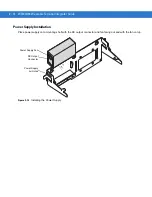
The AC line cord provides AC power to the power supply. The mounting bracket power cable provides power from
the power supply to the Four Slot Ethernet cradle and the Four Slot Spare Battery Charger. Ethernet cables (not
supplied) connects the cradle to the local network and to another cradle, if required.
Ensure that the AC line cord is long enough to reach from the AC power source to the power supply.
1.
Route the AC line cord through the right cable slot of the bracket.
2.
Plug the AC line cord into the power supply AC input connector.
3.
Route the power supply connector of the power cable through the cradle channel and out the left side of the
cradle.
4.
Plug the power cable connector into the DC output connector on the power supply.
5.
Plug the cradle power plug into the Four Slot Ethernet cradle input power connector.
6.
Plug the charger power plug onto the Four Slot Spare battery Charger input power connector.
7.
Plug one end of the Ethernet cable into the appropriate connector on the Four Slot Ethernet cradle.
8.
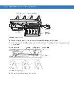
Route the cables as shown in
and
9.
Use two tie-wraps to secure the power cable Y connection to the power supply mounting shelf.
Mounting Studs
Mounting Slots
Summary of Contents for WT4090
Page 1: ...WT4070 90 Wearable Terminal Integrator Guide ...
Page 2: ......
Page 3: ...WT4070 90 Wearable Terminal Integrator Guide 72E 87638 07 Rev A April 2015 ...
Page 6: ...iv WT4070 90 Wearable Terminal Integrator Guide ...
Page 14: ...xii WT4070 90 Wearable Terminal Integrator Guide ...
Page 20: ...xviii WT4070 90 Wearable Terminal Integrator Guide ...
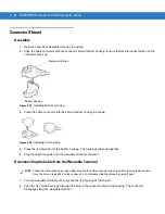
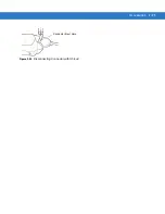
Page 55: ...Accessories 2 25 Figure 2 25 Disconnecting Connector with Shroud Connector Eject Hole ...
Page 56: ...2 26 WT4070 90 Wearable Terminal Integrator Guide ...
Page 62: ...3 6 WT4070 90 Wearable Terminal Integrator Guide ...
Page 66: ...4 4 WT4070 90 Wearable Terminal Integrator Guide ...
Page 138: ...6 32 WT4070 90 Wearable Terminal Integrator Guide ...
Page 162: ...8 2 WT4070 90 Wearable Terminal Integrator Guide ...
Page 166: ...9 4 WT4070 90 Wearable Terminal Integrator Guide ...
Page 190: ...A 12 WT4070 90 Wearable Terminal Integrator Guide ...
Page 205: ......

