background image

Glossary - 7

O

ODI. 

See 

Open Data-Link Interface

.

Open Data-Link Interface (ODI). 

Novell’s driver specification for an interface between network hardware and 

higher-level protocols. It supports multiple protocols on a single NIC (Network Interface Controller). It is capable of 
understanding and translating any network information or request sent by any other ODI-compatible protocol into 
something a NetWare client can understand and process.

Open System Authentication. 

Open System authentication is a null authentication algorithm.

P

PAN . 

Personal area network. Using Bluetooth wireless technology, PANs enable devices to communicate wirelessly. 

Generally, a wireless PAN consists of a dynamic group of less than 255 devices that communicate within about a 
33-foot range. Only devices within this limited area typically participate in the network. 

Parameter. 

A variable that can have different values assigned to it.

PING. 

(Packet Internet Groper) An Internet utility used to determine whether a particular IP address is online. It is used 

to test and debug a network by sending out a packet and waiting for a response.

Programming Mode. 

The state in which a scanner is configured for parameter values. See 

Scanning Mode

.

Q

Quiet Zone. 

A clear space, containing no dark marks, which precedes the start character of a bar code symbol and 

follows the stop character.

R

RAM. 

Random Access Memory. Data in RAM can be accessed in random order, and quickly written and read.

RF. 

Radio Frequency.

ROM. 

Read-Only Memory. Data stored in ROM cannot be changed or removed.

Router. 

A device that connects networks and supports the required protocols for packet filtering. Routers are typically 

used to extend the range of cabling and to organize the topology of a network into subnets. See 

Subnet

.

RS-232. 

An Electronic Industries Association (EIA) standard that defines the connector, connector pins, and signals 

used to transfer data serially from one device to another.

Summary of Contents for WT41N0

Page 1: ...WT41N0 WEARABLE TERMINAL INTEGRATOR GUIDE ...

Page 2: ......

Page 3: ...WT41N0 INTERGRATOR GUIDE 72E 160600 01 Rev A December 2012 ...

Page 4: ... copyright law The user shall not modify merge or incorporate any form or portion of a licensed program with other program material create a derivative work from a licensed program or use a licensed program in a network without written permission from Motorola The user agrees to maintain Motorola s copyright notice on the licensed programs delivered hereunder and to include the same on any authori...

Page 5: ...iii Revision History Changes to the original manual are listed below Change Date Description 01 Rev A 12 01 2012 Initial release ...

Page 6: ...iv WT41N0 Integrator Guide ...

Page 7: ...eatures 1 1 Getting Started 1 3 Installing and Removing the Main Battery 1 3 Installing the Main Battery 1 3 Charging the Battery 1 4 Charging the Main Battery and Backup Battery 1 4 Charging Spare Batteries 1 5 Removing the Main Battery 1 5 Starting the Wearable Terminal 1 6 WT41N0 Boot Up 1 6 Voice Only WT41N0 Boot Up 1 6 Checking Battery Status 1 8 Configuring the Wearable Terminal 1 8 Resettin...

Page 8: ...unication 2 12 Battery Charging Indicators 2 12 Speed LED 2 12 Link LED 2 12 2 12 Four Slot Spare Battery Charger 2 13 Spare Battery Charging 2 13 Battery Charging Indicators 2 14 Wall Mount Bracket 2 15 Power Supply Installation 2 16 Four Slot Ethernet Cradle Installation 2 17 Four Slot Battery Charger Installation 2 19 Wiring 2 19 Placing a Battery in the Charger 2 21 Mounting Multiple Brackets ...

Page 9: ...tion 6 2 Microsoft Bluetooth Stack 6 2 StoneStreet One Bluetooth Stack 6 2 FIPS 140 2 6 3 Bluetooth Configuration 6 3 Turning the Bluetooth Radio Mode On and Off 6 3 Disabling Bluetooth 6 4 Enabling Bluetooth 6 4 Bluetooth Power States 6 4 Cold Boot 6 4 Warm Boot 6 4 Suspend 6 5 Resume 6 5 MotoBTUI Application 6 5 Device Information 6 5 FIPS Configuration 6 6 Device Status 6 6 AccessingUsing the B...

Page 10: ...al COM Port Tab 6 28 HID Tab 6 28 Profiles 6 29 System Parameters 6 29 Miscellaneous Tab 6 29 Using the Microsoft Bluetooth Stack 6 30 Power Modes 6 30 Turning the Bluetooth Radio Mode On and Off 6 30 Disabling Bluetooth 6 30 Enabling Bluetooth 6 30 Discovering Bluetooth Device s 6 31 Available Services 6 32 Dial Up Networking 6 33 Bluetooth Printing 6 35 Headset Services 6 36 Chapter 7 Applicatio...

Page 11: ...reless LAN 8 3 Voice Only WT41N0 LED Considerations 8 3 Chapter 9 Maintenance Troubleshooting Introduction 9 1 Maintaining the Wearable Terminal 9 1 Wrist Mount Cleaning Instructions 9 2 Arm Sleeve Cleaning Instructions 9 2 Removing the Screen Protector 9 2 Battery Safety Guidelines 9 3 Cleaning 9 4 Materials Required 9 4 Cleaning the Wearable Terminal 9 4 Housing 9 4 Display 9 4 Connectors 9 4 Cl...

Page 12: ...fications A 1 Wearable Terminal A 1 RS309 Scanner A 3 RS409 Scanner A 4 RS419 Scanner A 5 RS507 Scanner A 6 Accessories A 8 Decode Zones A 12 RS309 A 12 RS409 A 16 RS419 A 19 RS507 A 21 DL A 21 SL A 23 Appendix B Software Setup Bluetooth Configuration Setting B 1 Glossary Index ...

Page 13: ... The documentation set for the WT41N0 is divided into guides that provide information for specific user needs WT41N0 Quick Start Guide provides information for using the WT41N0 wearable terminal Voice Only WT41N0 Quick Start Guide provides information for using the Voice Only WT41N0 wearable terminal WT41N0 User Guide describes how to operate the wearable terminal WT41N0 Integrator Guide describes...

Page 14: ...nformation icon 6 Press ENTER key to launch System Information applet Configuration Radios Display Memory Data Capture Operating System Keypads WT41N0 WLAN 802 11a b g n WPAN Bluetooth 2 8 QVGA Color non touch 2 GB Flash 512 MB RAM Optional accessory Windows CE 7 0 Professional Alphanumeric Keypad 2 8 QVGA Color touch 2 GB Flash 512 MB RAM Optional accessory Windows CE 7 0 Professional Alphanumeri...

Page 15: ...ovides instructions for using remote control software with the Voice Only WT41N0 Chapter 5 Wireless Applications provides instructions on using and configuring the wearable terminal on a wireless network Chapter 6 Bluetooth explains Bluetooth functionality on the wearable terminal Chapter 7 Application Development provides instructions for installing the Device Configuration Package and the SMDK f...

Page 16: ...ng documents provide more information about the WT41N0 wearable terminals WT41N0 Quick Start Guide p n 72 157178 xx Voice Only WT41N0 Quick Start Guide p n 72 162043 xx WT41N0 Regulatory Guide p n 72 159559 xx WT41N0 User Guide p n 72E 159561 xx RS309 Scanner Quick Reference Guide p n 72 86011 xx RS409 Scanner Quick Reference Guide p n 72 86010 xx RS419 Scanner Quick Reference Guide p n 72 158357 ...

Page 17: ...er Motorola Solutions responds to calls by email telephone or fax within the time limits set forth in support agreements If your problem cannot be solved by Motorola Solutions Global Customer Support you may need to return the equipment for servicing and will be given specific directions Motorola Solutions is not responsible for any damages incurred during shipment if the approved shipping contain...

Page 18: ...xvi WT41N0 Integrator Guide ...

Page 19: ...the shipping container for later storage and shipping Verify that you received all equipment listed below Wearable terminal Lithium ion battery Regulatory Guide Quick Start Guide Inspect the equipment for damage If you are missing any equipment or if you find any damaged equipment contact Motorola Solutions Global Customer Support immediately See Service Information on page xv for contact informat...

Page 20: ... WT41N0 Wearable Terminal Front View Application Keypad Display Programmable LED 2 Data Entry Keypad Power Button Action Keypad Speaker Microphone Charge Status LED Programmable LED 1 Charge Status LED WLAN Status LED Power Button Action Keypad Speaker Application Controlled LED Battery Status LED ...

Page 21: ... first time upon the wearable terminal s first power up the device boots and powers on automatically Battery Interface Connector Rubber Plug Interface Connector shown without Rubber Plug Cradle Connector Cleat Battery Release NOTE The main battery can be charged before or after installation into the wearable terminal Use the Single Slot USB cradle or Four Slot Spare Battery Charger to charge the m...

Page 22: ...remove the main battery from the wearable terminal for 16 hours to ensure that the backup battery fully charges If the main battery is removed from the wearable terminal or the main battery is fully discharged the memory backup battery completely discharges in several hours When the wearable terminal reaches a very low battery state the combination of main battery and backup battery retains data i...

Page 23: ...r accessory charge LED indicator definitions Removing the Main Battery To remove the main battery 1 Prior to removing the battery ensure that the wearable terminal is in suspend mode If the wearable terminal is not in suspend mode press the Power button to place the wearable terminal in suspend mode 2 Press the battery release button The battery partially ejects from the wearable terminal 3 Remove...

Page 24: ... screen appears for a short period of time followed by the Start Up window on non touch configurations and the calibration screen on touch enabled configurations Figure 1 6 Start Up Window App Launcher Voice Only WT41N0 Boot Up When the Voice Only WT41N0 is powered on the three LEDs on the front housing light in the sequence shown in Table 1 2 Battery Release NOTE When a battery is fully inserted ...

Page 25: ...wer icon to display the Battery Status window 2 Press ENTER To save battery power set the wearable terminal to turn off after a specified number of minutes Table 1 2 Voice Only WT41N0 Start Up LED Sequence Sequence Application Controlled LED Battery Charge LED WLAN Status LED 1 On On On 2 On On Off 3 Off Off Off 4 On Off Off 5 On On Off 6 On On On 7 On On Off 8 On Off Off 9 Off Off Off 10 Off Off ...

Page 26: ...he Power button for approximately five seconds As soon as the wearable terminal starts to perform a warm boot release the Power button Performing a Cold Boot A cold boot restarts the wearable terminal and erases all user stored records and entries that are not saved in flash memory Application and Platform folders Never perform a cold boot unless a warm boot does not solve the problem To perform a...

Page 27: ...ff the display backlight 6 Use the slider to set the brightness of the backlight Set it to a low value to save battery power 7 Press ENTER Changing the Keypad Backlight Settings To change the keypad backlight settings in order to conserve more battery power 1 Select Start Settings Control Panel Keylight icon Battery Power tab 2 Press ENTER NOTE To navigate using the keypad refer to the WT41N0 User...

Page 28: ...ess ALT w The Wireless menu appears 2 Select Enable Radio 3 Press ENTER Long Term Storage When storing the wearable terminal for a long period of time it is recommended to place the wearable terminal in storage mode 1 Remove the main battery 2 On the WT41N0 press and simultaneously hold the 1 9 keys and Power button cold boot or On the Voice Only WT41N0 press and simultaneously hold the P1 and P2 ...

Page 29: ...d and provides communication through an Ethernet connection Four Slot Spare Battery Charger Charges up to four spare batteries RS409 Scanner Provides 1D scanning capability RS419 Scanner Provides 1D scanning capability RS309 Scanner Provides 1D scanning capability RS507 Scanner Provides wired or wireless imaging capability Wrist Mount Provides a means for wearing the wearable terminal on the arm f...

Page 30: ... the Single slot cradle to USB hubs mice keyboards and memory The adapter has a USB mini A connector on the cradle side and a USB A Female connector on the other side Connector Shroud Protects the connector of an accessory that connects to the wearable computer Screen Protectors Package of 3 screen protectors Arm Sleeve Extra layer sleeve to wear under wrist mount for extra comfort and hygiene RCH...

Page 31: ... can also be used to synchronize the wearable terminal with corporate databases Charges the wearable terminal s battery Charges a spare battery Provides a location for storing an attached scanner during charging Figure 2 1 Single Slot USB Cradle Setup CAUTION Ensure that you follow the guidelines for battery safety described in Battery Safety Guidelines on page 9 3 NOTE The normal function of the ...

Page 32: ...dicates the status of the spare battery charging in the cradle See Table 2 2 for charging status indications The standard capacity batteries usually charge in less than four hours and the extended capacity battery usually charges in less than eight hours 1 2 Spare Battery Charge Status LED Table 2 2 Spare Battery Charge Status LED Indicator Spare Battery LED on cradle Indication Off No spare batte...

Page 33: ...oft ActiveSync Figure 2 3 ActiveSync Not Connected 3 In the ActiveSync window select File Connection Settings The Connection Settings window displays Figure 2 4 Connection Settings 4 Select Allow USB connection check box 5 Select OK to save any changes made 6 Connect the device to the host computer NOTE Every wearable terminal should have a unique device name Never try to synchronize more than one...

Page 34: ...minals with batteries installed The user cannot ActiveSync using the Four Slot Ethernet cradle To ActiveSync with a host computer use the Single Slot USB cradle Figure 2 5 Four Slot Ethernet Cradle CRD4000 4000ER Setup To setup the Ethernet cradle 1 Connect one end of an Ethernet cable to a Ethernet switch router or hub 2 Connect the other end of the Ethernet cable to the Ethernet Port 1 on the ba...

Page 35: ...y result The Speed LED and the Link LED on the Ethernet port 2 function in the same way as the Speed LED and the Link LED on the front of the cradle To daisychain cradles 1 Connect one end of the daisychain Ethernet cable either straight or twisted cable can be used to the Ethernet Port 2 port of the first cradle 2 Connect the other end of the Ethernet cable to the Ethernet Port 1 port on the seco...

Page 36: ...s lit to indicate that a link is established When it is not lit it indicates that there is no link CRD4001 4000ER Setup To setup the Ethernet cradle 1 Connect one end of an Ethernet cable to a Ethernet switch router or hub 2 Connect the other end of the Ethernet cable to the Primary Port on the back of the cradle 3 Connect the DC cable to the output of the power supply Ethernet Port 1 Ethernet Por...

Page 37: ...throughput issues will certainly result The LEDs on the Primary Ethernet port function in the same way as the LEDs on the front of the cradle To daisychain cradles 1 Lift or remove the label covering the Secondary Port on the back of the first cradle 2 Connect one end of the daisychain Ethernet cable either straight or twisted cable can be used to the Secondary Port of the first cradle 3 Connect t...

Page 38: ...pre installed on the wearable terminal and initiate automatically when the wearable terminal is placed in a properly connected Four Slot Ethernet cradle When the wearable terminal is inserted into the Four Slot Ethernet cradle the LAN icon appears in the taskbar and indicates that the wearable terminal is connected to a network Secondary Port Primary Port 1st Cradle 2nd Cradle Ethernet Cable To Po...

Page 39: ...the WT41N0 open a Command Prompt window and enter ipconfig 1 Press CTRL ESC 2 Use the navigation keys to select Programs 3 Press ENTER to open the sub menu 4 Use the navigation keys to select Command Prompt 5 Press ENTER The Command Prompt window displays 6 Enter ipconfig The window displays the IP Address assigned to the wearable terminal Figure 2 10 Ethernet IP Address NOTE The device s IP addre...

Page 40: ...ors The wearable terminal s amber Charge Status LED shows the status of the battery charging in the wearable terminal See Table 1 1 on page 1 5 for charging status indications The standard capacity battery usually charges in less than four hours and the extended capacity battery usually charges in less than eight hours ...

Page 41: ...and press down on the battery to ensure proper contact Figure 2 13 Spare Battery Charging CAUTION Ensure that you follow the guidelines for battery safety described in Battery Safety Guidelines on page 9 3 CAUTION Use only a Motorola approved power supply output rated 12 VDC and minimum 3 3 A Use of an alternative power supply will void the product warranty and may cause product damage Refer to th...

Page 42: ...han four hours and the extended capacity battery usually charges in less than eight hours Table 2 5 Spare Battery Charge Status LED Indicators LED Indication Off No spare battery in slot spare battery not placed correctly cradle is not powered Fast Blinking Amber Charging error Temperature is too low or too high Charging has gone on too long without completing typically eight hours Slow Blinking A...

Page 43: ...et onto the wall level and mark the five screw hole locations 1 Install top three screws into the wall 2 Align the top three mounting holes with the screws 3 Place mounting bracket on screws 4 Secure the mounting bracket to the wall by tightening the three screws 5 Install and secure two screws at the bottom of the bracket Figure 2 14 Mounting the Bracket Right Cable Slot Left Cable Slot Power Sup...

Page 44: ...er Supply Installation Place power supply onto mounting shelf with the DC output connector and fan facing out and with the fan on top Figure 2 15 Installing the Power Supply Power Supply Fan DC Output Connector Power Supply Air Holes ...

Page 45: ...ots in the back of the cradle with the two cradle alignment tabs on the bracket Figure 2 16 Aligning the Slots in the Cradle with Mounting Bracket Tabs 2 Secure the cradle to the mounting bracket with two M4 0 screws supplied with the bracket Cradle Alignment Tab Cradle Slots ...

Page 46: ...2 18 WT41N0 Integrator Guide Figure 2 17 Securing the Four Slot Ethernet Cradle to the Mounting Bracket ...

Page 47: ...k and to another cradle if required Ensure that the AC line cord is long enough to reach from the AC power source to the power supply 1 Route the AC line cord through the right cable slot of the bracket 2 Plug the AC line cord into the power supply AC input connector 3 Route the power supply connector of the power cable through the cradle channel and out the left side of the cradle 4 Plug the powe...

Page 48: ... Use two tie wraps to secure the charger power lead the AC line cord and Ethernet cable if required together as shown below Figure 2 20 Routing Cables 12 Plug the AC line cord into an AC power source Cradle Power Plug Right Cable Slot Charger Power Plug Tie Wraps Ethernet Cable Plug AC Line Cord Tie Wraps Tie Wrap Charger Power Lead Ethernet Cable ...

Page 49: ...to the Battery Charger Mounting Multiple Brackets When installing multiple brackets on a wall Each mounting bracket must be 25 4 cm 10 in from the top of one bracket to the top of the next bracket The bottom of the last bracket must be at least 61 cm 24 in from the floor When mounting brackets next to each other the tabs must at least touch each other to ensure minimum distance between brackets ...

Page 50: ...2 22 WT41N0 Integrator Guide Figure 2 22 Installing Multiple Mounting Brackets 61 cm 24 in 25 4 cm 10 in Position Tabs Together to Ensure Minimum Distance ...

Page 51: ...ector on the other end a USB device a USB keyboard a USB mouse a USB hub optional Connect the mini USB A connector end into the USB connector on the back of the Single Slot USB cradle The cradle automatically detects the USB A connector and places the wearable terminal into USB host mode Connect the USB device mouse or keyboard connector into the USB A Female connector You can also connect both a ...

Page 52: ... USB Keyboard Connection to the Single Slot USB Cradle Figure 2 25 USB Mouse Keyboard Hub Connection to the Single Slot USB Cradle Mini USB A USB A Female USB Keyboard USB Cable Mini USB A USB A Female USB Hub USB Mouse USB Keyboard USB Cable ...

Page 53: ... together 5 Plug the cable connector into the wearable terminal connector Disconnecting the Cable from the Wearable Terminal 1 Turn the wearable terminal over to expose the top housing of the shroud 2 Push the tip of a ball point pen through the hole in the connector shroud top housing The connector disengages from the wearable terminal NOTE Use only on the RS409 or RS419 with extended cable Disco...

Page 54: ...2 26 WT41N0 Integrator Guide Figure 2 28 Disconnecting Connector with Shroud Connector Eject Hole ...

Page 55: ...s between the WT41N0 and the host computer converting the files to the correct format Backs up the data stored on the WT41N0 Synchronization is a one step procedure that ensures the data is always safe and up to date Copies rather than synchronizes files between the WT41N0 and the host computer Controls when synchronization occurs by selecting a synchronization mode For example synchronize continu...

Page 56: ...p the Change Connection button 3 Select the connection type from the drop down list 4 Tap OK to exit the Change Connection window and tap OK to exit the PC Connection Properties window 5 Proceed with installing ActiveSync or WMDC on the host computer and setting up a partnership Setting Up a Sync Connection Set up a Sync connection using Windows XP or Windows 7 ActiveSync Windows XP To set up a Sy...

Page 57: ...check box 5 Select OK to save any changes made Windows Mobile Device Center Windows 7 To set up a Sync connection using Windows 7 1 Select Start All Programs Windows Mobile Device Center on the host computer Figure 3 4 Windows Mobile Device Center Window 2 In the WMDC window under Mobile Device Settings click Connection settings NOTE Assign each WT41N0 a unique device name Do not try to synchroniz...

Page 58: ...tting up a Partnership To set up a partnership 1 If the Get Connected window does not appear on the host computer select Start All Programs Microsoft ActiveSync 2 Select if you want to create synchronize with the host computer or to connect as a guest 3 Click Next Figure 3 6 Select Synchronization Setting Window 4 Select the appropriate settings and click Next ActiveSync WMDC ...

Page 59: ...nnect from the host computer For more information about using ActiveSync or WMDC start the application on the host computer then see Help ActiveSync WMDC ActiveSync WMDC NOTE The first synchronization operation must be performed with a local direct connection To retain partnerships after a cold boot capture partnership registry information in a reg file and save it in the Flash File System detaile...

Page 60: ...3 6 WT41N0 Integrator Guide ...

Page 61: ... with the software to install on a host computer Ensure that ActiveSync is installed on the host computer See Chapter 3 Synchronization for more information Connection to Host Computer To connect the Voice Only WT41N0 to a host computer 1 Connect the Single Slot Serial USB cradle to the host computer See Single Slot USB Cradle on page 2 3 for setup instructions 2 Insert the Voice Only WT41N0 into ...

Page 62: ...the host computer click Start Programs Motorola MSP MotoRC Run Motorola Remote Control The Run Motorola Remote Control DOS window opens followed by the Motorola Remote Control window Figure 4 1 Motorola Remote Control Window 2 Click on the UI Control icon to display the Voice Only WT41N0 desktop UI Control Icon ...

Page 63: ...ow Microsoft ActiveSync Remote Display Connection To control the Voice Only WT41N0 using the Microsoft ActiveSync Remote Display software 1 On the host computer click Start Programs ActiveSync Remote Display The ActiveSync Remote Display window displays with the Voice Only WT41N0 desktop shown Figure 4 3 ActiveSync Remote Display Window 2 Use the host computer mouse to control the Voice Only WT41N...

Page 64: ...4 4 WT41N0 Integrator Guide ...

Page 65: ...onfigure and test the wireless radio in the WT41N0 Refer to the Wireless Fusion Enterprise Mobility Suite User Guide for Version X2 00 for information on configuring wireless profiles Go to http supportcentral motorola com for the latest version of this guide See Software Versions on page xii to determine the Fusion version on the WT41N0 Tap the Signal Strength icon to display the Wireless Launche...

Page 66: ...ation Options Invokes the Options application which allows you to configure the Fusion option settings Wireless Status Invokes the Wireless Status application which allows you to view the status of the current wireless connection Wireless Diagnostics Invokes the Wireless Diagnostics application which provides tools with which to diagnose problems with the wireless connection Log On Off Invokes the...

Page 67: ... appears 2 Use the navigation keys to select Disable Radio 3 Press ENTER Figure 5 3 Fusion Menu To turn on the WLAN radio 1 Press ALT W Out of network range not associated No WLAN network connection Notify the network administrator The WLAN radio is disabled The WLAN radio is disabled To enable choose Enable Radio from the Wireless Applications menu None The Wireless Launcher application was exite...

Page 68: ...ofile It is recommended that you read the profile editor chapter 1 Find out from your IT administrator what the connection settings should be Extended Service Set Identifier ESSID Enterprise or Personal authentication type tunnel type certificate requirements Protected Access Credentials PAC requirements Note that not all of the items listed may be relevant 2 Create the profile using the informati...

Page 69: ...Hopping Adaptive Frequency Hopping AFH is a method of avoiding fixed frequency interferers AFH can be used with Bluetooth voice All devices in the piconet Bluetooth network must be AFH capable in order for AFH to work There is no AFH when connecting and discovering devices Avoid making Bluetooth connections and discoveries during critical 802 11b communications AFH for Bluetooth can be broken down...

Page 70: ...number is never sent over the air By default the Bluetooth stack responds with no key when a key is requested it is up to user to respond to the key request event Authentication of Bluetooth devices is based upon a challenge response transaction Bluetooth allows for a PIN number or passkey that is used to create other 128 bit keys used for security and encryption The encryption key is derived from...

Page 71: ...etooth stack and the Microsoft Bluetooth stack Table 6 2 lists the COM ports available for the StoneStreet One and Microsoft Bluetooth stacks Table 6 1 Bluetooth Services Features Microsoft Bluetooth Stack StoneStreet One Bluetooth Stack GAP Profile Yes Yes SDP Profile Yes Yes Serial Port Profile Server and Client Yes Yes Headset Profile Audio Gateway Yes Yes Dialup Networking Profile Client Role ...

Page 72: ...etooth connection that was dropped during a suspend needs to be reconnected after a resume MotoBTUI Application Use the MotoBTUI application to Turn the Bluetooth radio on and off View device information Control device status Generate a pairing bar code Refer to the RS507 Product Reference Guide for more information Configure FIPS key Discover and pair with other Bluetooth devices using the Micros...

Page 73: ...return to the MotoBTUI window To generate a new FIPS key manually 1 Tap Start Programs MotoUI 2 Tap FIPS Configuration 3 Tap Enter Key button 4 In the text box enter a key 5 Tap the SetUp Key button A new key is generated The key file NewAESKey reg is created in the Application folder 6 Tap the Back button to return to the MotoBTUI window To transfer the new FIPS key to another Bluetooth device 1 ...

Page 74: ...the filename The RegMerge confirmation box displays 4 Tap Yes 5 Perform a warm boot Device Status Use the Device Status option to set if the WT41N0 would be seem by other Bluetooth devices Select the Device Status option to toggle the WT41N0 from Hidden to Discoverable ...

Page 75: ... Bluetooth devices within range Communicate only with Bluetooth radios in close proximity Disabling Bluetooth To disable Bluetooth press ALT B Use the navigation keys to select Disable Bluetooth Press ENTER An exclamation point appears on the Bluetooth icon indicating that the Bluetooth radio is disabled Figure 6 2 Disable Bluetooth Enabling Bluetooth To enable Bluetooth press ALT B Use the naviga...

Page 76: ...ed device and navigation within the BTExplorer application is performed using the keypad Refer to the WT41N0 User Guide for detailed information on keypad navigation Key Combinations The wearable terminal with non touch display uses special key combinations to easily navigate applications Table 6 4 lists the key combinations required to perform various application navigation and control functions ...

Page 77: ...See Using the StoneStreet One Bluetooth Stack on page 6 7 6 From the Favorite window a Press ALT F to open the File menu b Use the navigation keys to select New Connection and press ENTER The New Connection Wizard window appears Table 6 4 Key Combinations Action Combination Access the Start menu on the taskbar CTRL ESC Switch fields within an application TAB Close windows or cancel operations on s...

Page 78: ...t using Phone Modem Connect to Personal Area Network Connect to Printer Send or Exchange Objects Associate Serial Port 8 Press ENTER BTExplorer searches for Bluetooth devices in the area and displays the devices in the Select Remote Device window Figure 6 6 Device Discovery Dialog Box NOTE If a device discovery action has not been previously performed a device discovery is automatically initiated ...

Page 79: ... press ENTER The Connection Favorite Options window appears Figure 6 9 Connection Favorite Options Window 11 Press TAB to highlight the Favorite Name text box enter a name for this service that will appear in the Favorite window 12 Press ENTER The Connection Summary window appears NOTE To filter devices in the list press ALT F to open the filter menu Select a device type and then press ENTER To ch...

Page 80: ...s Headset Services OBEX Object Push Services Serial Port Services Personal Area Network Services HID Services These services are discussed in the following paragraphs File Transfer Services To transfer files between the wearable terminal and another Bluetooth enabled device 1 In the Favorite window use the navigation keys to select the file transfer service 2 Press MENU and select Connect from the...

Page 81: ...ction to perform a New create a new file or folder on the remote device b Delete delete the selected file on the remote device c Get File copy the file from the remote device to the wearable terminal d Put File copies a file from the wearable terminal to the remote device e Parent Directory opens the higher level folder f Refresh re displays the files in the current folder Create New File or Folde...

Page 82: ...e the navigation keys to select Delete 4 Press ENTER A Delete Remote Device File dialog box appears 5 Press ENTER to delete the file Get File To copy a file from a remote device to the wearable terminal 1 Press MENU to open the pop up menu 2 Use the navigation keys to select Get File 3 Press ENTER The Save Remote File window appears Figure 6 15 Save Remote File Window 4 Press TAB three times to en...

Page 83: ...ile window appears Figure 6 17 Sending Local File Window 8 The file is transferred from the wearable terminal to the remote device Connect to Internet Using Access Point This section explains how to access a Bluetooth enabled LAN access point AP for a network connection With this method of communication the Internet Explorer can be used to connect to a server 1 In the Favorite window use the navig...

Page 84: ...the pop up menu 3 Press ENTER The OBEX Object Push window appears Figure 6 18 OBEX Object Push Window 4 Press TAB twice to highlight the button 5 Press SPACE 6 The Send Local Picture window appears Figure 6 19 Send Local Picture Window 7 Press TAB three times to enter the folder area 8 Using the navigation keys to highlight a file and press ENTER The OBEX Object Push window appears To open a folde...

Page 85: ...uld a physical serial cable connection You must configure the application that will use the connection to the correct serial port To establish a serial port connection 1 In the Favorite window use the navigation keys to select the Serial Port service 2 Press MENU and select Connect from the pop up menu 3 Press ENTER 4 The Remote Service Connection window appears Figure 6 21 Remote Service Connecti...

Page 86: ...nal and another Bluetooth device in order to exchange information in a secure manner Creating a bond involves entering the same PIN on the two devices to bond Once a bond is created and the Bluetooth radios are turned on the devices recognize the bond and are able to exchange information without re entering a PIN To bond with a discovered Bluetooth device 1 Access BTExplorer See Using the StoneStr...

Page 87: ...Figure 6 25 Pairing Status Window 9 Press P2 The devices are successfully paired The device name moves to the Trusted Devices window NOTE Devices discovered previously are listed to save time To start a new device discovery press Menu select Discover Devices from the menu and press ENTER NOTE To filter devices in the list press ALT F to open the filter menu Select a device type and then press ENTE...

Page 88: ...e PIN must be between 1 and 16 characters 4 Press ENTER The bond is created and the wearable terminal can now exchange information with the other device Trusted Devices Window The Trusted Devices window lists all bonded devices To access the Trusted Devices window 1 Launch BTExplorer 2 Press ALT T 3 Using the navigation keys select Trusted Devices 4 Press ENTER The Trusted Devices window appears F...

Page 89: ...dialog box appears 5 Press ENTER to confirm deletion of the trusted device 6 Press ENTER to exit the Trusted Device window Connecting to a Favorite Service The Favorite window can display many services set as favorites To connect to one of these services 1 Use the navigation keys to select the service 2 Press ENTER 3 The wearable computer connects to the service The service icon text becomes highl...

Page 90: ... Services To delete all favorites from the Favorites window 1 Press ALT F 2 Use the navigation keys to select Delete All Favorites 3 Press ENTER A confirmation dialog box appears 4 Press ENTER to confirm the deletion or ESC to cancel the deletion Delete a Favorite Service To delete a selected favorite 1 Use the navigation keys to select a favorite 2 Press MENU The pop up menu appears 3 Use the dow...

Page 91: ...Press ALT T 2 Use the down arrow key to select Local Device Properties 3 Press ENTER The Local Device Property window appears 4 Press ENTER to close the window Bluetooth Settings Use the BTExplorer Settings window to configure the operation of the BTExplorer application To access the settings press ALT T use the navigation keys to select Settings Press ENTER The BTExplorer Settings window appears ...

Page 92: ...Service window displays Table 6 5 Device Info Tab Field Description Device Name Displays the name of the wearable terminal Not editable Discoverable Mode Allows you to set the wearable terminal to be discoverable by other Bluetooth devices or not be discoverable Note For security reasons the default is set to Non Discoverable Connectable Mode Allows you to set the wearable terminal to be connectab...

Page 93: ...uetooth devices to browse files Figure 6 34 BTExplorer Settings File Transfer Information Headset Audio Gateway Service Headset Service Audio Gateway allows connection to headset devices Table 6 6 File Transfer Information Data Item Description Service Name Displays the name of the service Service Security Select the type of security from the drop down list Options are None Authenticate or Authent...

Page 94: ...able 6 8 OBEX Exchange Information Data Item Description Service Name Displays the name of the service Service Security Select the type of security from the drop down list Options are None Authenticate or Authenticate Encrypt Do not allow clients to push objects Disables clients from pushing objects to the WT41N0 Inbox Directory Select a directory where another Bluetooth device can store files Bus...

Page 95: ...ame of the service Service Security Select the type of security from the drop down list Options are None Authenticate or Authenticate Encrypt Local COM Port Select the COM port Local Baud Rate Select the communication baud rate Local Port Options Select the port option NOTE To use PIN Code select Authenticate or Authenticate Encrypt from the Service Security drop down list on each local service Ta...

Page 96: ... Item Description Inquiry Length Sets the amount of time the wearable terminal takes to discover Bluetooth devices in the area Name Discovery Mode Select either Automatic or Manual to automatically attempt to discover a Bluetooth device s name after finding the device Discovered Devices Delete Devices Deletes all discovered devices and link keys from memory Discovered Devices Delete Linked Keys Re...

Page 97: ... Delay slider to the left Rate To increase key repeat speed drag the Rate slider to the left To decrease key repeat speed drag the Rate slider to the right Table 6 15 HID Tab Item Description Page Timeout Sets the amount of time the wearable terminal searches for a device before moving on to the next device Link Supervision Timeout Sets the amount of time that the wearable terminal will wait for a...

Page 98: ...lane When the radio is off the wearable terminal can not be seen by or connected to other Bluetooth devices Turn on the Bluetooth radio to exchange information with other Bluetooth devices within range Communicate only with Bluetooth radios in close proximity Disabling Bluetooth To disable Bluetooth select Start Settings Control Panel MotoBTUI and then select On icon in the top left corner Figure ...

Page 99: ...e Bluetooth device to discover is in discoverable and connectable modes 3 Ensure that the two devices are within 10 meters 32 8 feet of one another 4 Select Start Programs MotoBTUI Figure 6 39 MotoBTUI Window 5 If Bluetooth is off select the Bluetooth icon to turn Bluetooth on 6 Select the Connections tab The wearable terminal begins searching for discoverable Bluetooth devices in the area Discove...

Page 100: ...ything on the other device 14 When the connection is complete a list of matching and supported services on the device appears 15 Select the services you want to use and tap Finish The services on the new devices have to be selected or else the pairing won t include those services even though the devices are paired If services are not selected you will be continually re prompted for the passcode fr...

Page 101: ...ol Panel MotoBTUI 4 If Bluetooth is off select the Bluetooth icon to turn Bluetooth on 5 Select the Connections tab The wearable terminal begins searching for discoverable Bluetooth devices in the area Discovered devices appear in the list Figure 6 43 Searching for Bluetooth Devices 6 Use the navigation key to select a Bluetooth device 7 Press ENTER The Services window displays 8 Pair and activate...

Page 102: ...hout Graphics Headset Services To connect to a Bluetooth headset 1 If the wearable computer is not paired with a Bluetooth headset see Discovering Bluetooth Device s on page 6 31 2 Tap Start Settings Control Panel MotoBTUI 3 If Bluetooth is off select the Bluetooth icon to turn Bluetooth on 4 Select the Connections tab The wearable terminal lists paired and available Bluetooth devices 5 Use the na...

Page 103: ...6 1 or higher for Windows 7 Install one or more of the following Microsoft Visual Studio 2005 with Service Pack 1 Microsoft Visual Studio 2008 with Service Pack 1 Enterprise Mobility Developer Kit EMDK for C The EMDK for C is a development tool used to create native C and C applications for all Motorola Solutions devices It includes documentation header files H and library files LIB for native cod...

Page 104: ...er Kit for C program group of the Windows Start menu 4 The sample applications provide examples of how to interface with the Motorola API functions To build a sample application open the Samples folder from the Windows Start menu Open the folder for the desired sample and then open the project file The project file has an extension of vcproj Microsoft Visual Studio automatically launches Select Wi...

Page 105: ...ained even when the wearable terminal is cold booted just as the Sample Applications program is retained in memory There are two device drivers included in the Windows CE image to assist developers in configuring the wearable terminal following a cold boot RegMerge and CopyFiles RegMerge dll RegMerge dll is a built in driver that allows registry edits to be made to the Windows CE registry Regmerge...

Page 106: ...en the operating system is running They also contain system information Non FFS partitions include the following Windows CE The complete Windows CE operating system is stored on Flash devices If necessary the entire OS image may be downloaded to the wearable terminal using files provided by Motorola Any upgrades must be obtained from Motorola This partition is mandatory for the wearable terminal S...

Page 107: ...artition is updated all data that was previously in its storage region is erased i e it is not a merge but rather a replacement operation Typically the operating system is not running when partitions are update so Bootloader can perform partition updates All partition images suitable for use by Bootloader are in hex file format for transfer by USBDownloader from the development computer to the wea...

Page 108: ...le slot USB cradle or an appropriate cable See Chapter 2 Accessories for connection information 3 On the host computer select Start Programs ActiveSync Figure 7 1 ActiveSync Connected Window 4 Select Explore Figure 7 2 ActiveSync Explorer 5 Double click the folder to expand the folder contents ...

Page 109: ... 1 On the wearable terminal select Start Settings Control Panel USBConfig Figure 7 4 USBConfig Window 2 On the USB Port Mode tab select USB Client Mode 3 On the USB Client Mode tab select Mass Storage 4 In the drop down list select Platform or Application 5 Select OK 6 Connect the wearable terminal to a host computer using either a Single slot USB cradle or a USB ActiveSync Charge cable 7 On the h...

Page 110: ...rm on page 7 15 for information OSUpdate Loader Operating system component can be downloaded to the wearable terminal using the Temp folder Using the Temp Folder To initiate an update using the wearable terminal Temp folder 1 Go to the Support Central web site http supportcentral motorola com and download the appropriate update package 2 Connect the wearable terminal to a host computer using the S...

Page 111: ... the flash memory of the WT41N0 To load the hex files on to the WT41N0 using USB 1 Download the USBDownload application from the Support Central web site Follow the installation instructions with the application 2 Connect the WT41N0 to a host computer using the Single slot USB Cradle or USB ActiveSync Charge Cable 3 On the host computer launch the USBDownload application Figure 7 6 USB Download Wi...

Page 112: ...CAUTION To ensure a successful download do not remove power from the WT41N0 while in Bootloader Waiting for input Bootloader 1 02 0000 NOTE One hex file or multiple hex files can be selected To select multiple files press the Ctrl key while selecting files If selecting multiple files to download USBDownload reads the header of the file and identifies the file type If the Partition table file is am...

Page 113: ...mized flash file system partitions to the Voice Only WT41N0 and load hex files to the flash memory of the WT41N0 To load the hex files on to the Voice Only WT41N0 using USB 1 Download the USBDownload application from the Support Central web site Follow the installation instructions with the application 2 Connect the Voice Only WT41N0 to a host computer using the Single slot USB Cradle or USB Activ...

Page 114: ...e File Window 7 Select the hex files and the click Open CAUTION To ensure a successful download do not remove power from the Voice Only WT41N0 while in Bootloader NOTE One hex file or multiple hex files can be selected To select multiple files press the Ctrl key while selecting files If selecting multiple files to download USBDownload reads the header of the file and identifies the file type If th...

Page 115: ...or a new selection To find the probable cause of the error use the error number and or the error text displayed on the screen to look up the error in Table 7 1 NOTE If an invalid image is selected the LEDs blink three times Table 7 1 Bootloader Errors Error Text Error Number Probable Cause Unknown error 1 A general error occurred Retry the download If the failure persists it is most likely due to ...

Page 116: ...icient data available to complete record 21 A HEX file download was attempted but the HEX file is invalid Ensure the file is in proper HEX file format Invalid Symbol HEX file 23 A HEX file download was attempted but the HEX file is invalid Ensure the file is in proper HEX file format Unrecognized or unsupported HEX record 24 The HEX file being downloaded contains an invalid or unrecognized HEX rec...

Page 117: ...256 2 Modify the bitmap file and save To load the splash screen 1 Convert the bmp file into a hex file using the OSUpdate Package Builder that is part of MSP 2 Copy the hex file to the wearable terminal using BootLoader See Bootloader on page 7 9 Timed Out No data 31 Bootloader was waiting for data from the source device but timed out before receiving any Check the source device connectivity and r...

Page 118: ...7 16 WT41N0 Integrator Guide ...

Page 119: ... overlay Keep the touch points at least 2 mm in from the edge Tips for Improving Battery Life To improve the life of the battery Set the display backlight to turn off quickly and reduce the display brightness Set the keypad backlight to turn off quickly Set the wearable computer to suspend when not in use and maximum CPU performance Set the WLAN radio to save maximum power After making these setti...

Page 120: ... 1 minute or a lower value that the user is comfortable with To disable the key light from coming on 1 Select the Advanced tab 2 Ensure that the Disable keylight checkbox is checked Tap OK Power To set the wearable computer to turn off after a short period of non use 1 Select Start Settings Control Panel 2 Select Power icon 3 Select Advanced tab 4 Ensure that the Turn off device if not used for ch...

Page 121: ...dit 6 Continuously select Next until the Battery Usage Mode window appears 7 Ensure the MAX Power Save radio button is selected Voice Only WT41N0 LED Considerations Application developers for the Voice Only WT41N0 should not program all LEDs to be turned on at the same time as this sequence is reserved for IPL mode Consider device battery life when programming LED blinking Refer to the EMDK Help f...

Page 122: ...8 4 WT41N0 Integrator Guide ...

Page 123: ...able computer touch screen Motorola requires using this to minimize wear and tear Screen protectors enhance the usability and durability of touch screen displays Benefits include Protection from scratches and gouges Durable touch surface with tactile feel Abrasion and chemical resistance Keeping the device s screen looking new Quick and easy installation Protect the wearable computer with a touch ...

Page 124: ... arm sleeve when it become soiled Hand wash in cold water with a mild detergent such as Woolite Do not use bleach Air dry Do not use a dryer Removing the Screen Protector A screen protector is applied to the wearable terminal with touch screen Motorola mandates using this to minimize wear and tear Screen protectors enhance the usability and durability of touch screen displays To remove the screen ...

Page 125: ...y support Do not disassemble or open crush bend or deform puncture or shred Severe impact from dropping any battery operated device on a hard surface could cause the battery to overheat Do not short circuit a battery or allow metallic or conductive objects to contact the battery terminals Do not modify or remanufacture attempt to insert foreign objects into the battery immerse or expose to water o...

Page 126: ...uld be taken not to allow any pooling of liquid around the edges of the display Immediately dry the display with a soft non abrasive cloth to prevent streaking For WT41N0 with touch panel only use a soft lens cloth to clean the touch panel overlay surface Connectors Clean all three connectors two interface connectors on the sides of the wearable terminal and the cradle connector on the back 1 Remo...

Page 127: ... exit window periodically with a lens cloth or other material suitable for cleaning optical material such as eyeglasses Connectors 1 Disconnect the scanner from mobile computer 2 Dip the cotton portion of the cotton tipped applicator in isopropyl alcohol 3 Rub the cotton portion of the cotton tipped applicator back and forth across the connector pins Do not leave any cotton residue on the connecto...

Page 128: ...f the temperature is low and humidity is high longer drying time is required Warm temperature and dry humidity requires less drying time Cleaning Frequency The cleaning frequency is up to the customer s discretion due to the varied environments in which the mobile devices are used They may be cleaned as frequently as required However when used in dirty environments it may be advisable to periodica...

Page 129: ...ion Screen protector may be scratched or worn Replace screen protector During data communication no data was transmitted or transmitted data was incomplete Wearable terminal removed from cradle or unplugged from host computer during communication Replace the wearable terminal in the cradle or reattach the Synchronization cable and re transmit Incorrect cable configuration See the System Administra...

Page 130: ...d Battery is depleted Replace or recharge the battery Battery is not inserted properly Insert the battery properly see Installing and Removing the Main Battery on page 1 3 The wearable computer s battery is low and it powers down to protect memory content Replace or recharge the battery A message appears stating that the wearable terminal memory is full not applicable to voice only configuration T...

Page 131: ...the scanner shuts off before the wearable terminal low battery condition notification Note If the scanner is still not reading symbols contact the distributor or Motorola Wearable terminal goes into IPL mode after cold boot Headset adapter without a headset is connected to the wearable terminal during a cold boot Disconnect the headset adapter prior to performing a cold boot Scanner trigger is hel...

Page 132: ... Ethernet Cradle Problem Cause Solution Wearable terminal amber Charge Status LED does not light when wearable terminal inserted Cradle is not receiving power Ensure the power cable is connected securely to both the cradle and to AC power Wearable terminal is not correctly seated Remove and re insert the wearable terminal into the cradle ensuring it is correctly seated Wearable terminal battery is...

Page 133: ... seated firmly in the cradle Remove and re insert the spare battery into the charging slot ensuring it is firmly seated Wearable terminal battery is not charging Wearable terminal was removed from cradle or cradle was unplugged from AC power too soon Ensure cradle is receiving power Ensure wearable terminal is seated correctly Confirm main battery is charging View battery status by selecting Start...

Page 134: ...sories Ensure that Microsoft ActiveSync 4 1 or greater is installed on the host computer Cannot ActiveSync with Host Computer Wrong USB cable used Ensure that the cable has a USB A connector on one end and a USB mini B connector on the other end Host computer not configured properly Ensure that ActiveSync on the host computer is set to allow USB connections The wearable computer is not fully seate...

Page 135: ... 6 cm H 5 7 inches L x 3 7 inches W x 1 0 inch H With Extended Battery 14 2 cm L x 10 7 cm H x 2 6 cm H 5 7 inches L x 4 2 inches W x 1 0 inch H Weight including battery With Standard Battery 320 g 11 3 oz With Extended Battery 369 g 13 0 oz Keyboard WT41N0 Alphanumeric Keypad Voice Only WT41N0 Three programmable function keys Display WT41N0 Color 2 8 inch QVGA non touch or touch screens Voice Onl...

Page 136: ...C indirect discharge WLAN Wireless Data Communications WLAN radio 802 11a b g n Operating Channels Channel 8 169 5040 5845 MHz 4920 4980 MHz Japan only Channel 1 13 2412 2472 MHz Channel 14 2484 MHz Japan only Actual operating frequencies depend on regulatory rules and certification agency Security Security Modes Legacy WPA and WPA2 Encryption WEP 40 or 128 bit TKIP and AES Authentication TLS TTLS...

Page 137: ...s Dimensions standard version without cables attached 6 8 cm L x 6 1 cm H x 3 8 cm 2 7 inch L x 2 4 inch W x 1 5 inch H Weight standard version without cables attached 98 g 3 525 oz Current 140 mA typical 180 mA max Standby Current 60 μA max Voltage 3 1 to 3 6 VDC Vcc Noise Level 200 mV p p max Performance Characteristics Light Source 650 nm LASER 1 06 mW Scan Rate 35 5 scans sec bidirectional Yaw...

Page 138: ...409 Technical Specifications Item Description Physical and Environmental Characteristics Dimensions 4 8 cm L x 3 6 cm H x 4 8 cm H 1 9 in L x 1 4 in W x 1 9 in H Weight standard version without cables attached 56 7 gm 2 0 oz Current 92 mA typical 121 mA max Standby Current 12 μA typical 60 μA max Voltage 3 1 to 3 6 VDC Vcc Noise Level 100 mV p p max Performance Characteristics Light Source 650 nm ...

Page 139: ... Specifications Item Description Physical and Environmental Characteristics Dimensions 4 8 cm L x 3 6 cm H x 4 8 cm H 1 9 in L x 1 4 in W x 1 9 in H Weight standard version without cables attached 56 7 gm 2 0 oz Current 92 mA typical 121 mA max Standby Current 12μA typical 60 μA max Voltage 3 1 to 3 6 VDC Vcc Noise Level 100 mV p p max Performance Characteristics Light Source 650 nm LASER 1 77 mW ...

Page 140: ...dard battery 2 9 x 5 3 x 7 4 cm 1 16 x 2 1 x 2 92 in Triggerless extended battery 3 6 x 5 3 x 7 4 cm 1 42 x 2 1 x 2 92 in Triggered standard battery 2 9 x 5 3 x 7 4 cm 1 16 x 2 1 x 2 92 in Triggered corded cord length not included 3 3 x 5 3 x 7 4 cm 1 3 x 2 1 x 2 92 in Weight Triggerless standard battery 121 4 g 4 3 oz Triggerless extended battery 146 4 g 5 2 oz Triggered standard battery 134 8 g ...

Page 141: ...ss Bluetooth Class II v 2 1 with Adaptive Frequency Hopping AFH Supported profiles Serial Port Profile SPP Human Interface Device Profile HID Service Discovery Application Profile SDAP Pairing by reading terminal BT address as bar code off the display or from a printed label Corded to WT41N0 Serial User Interface LED Two parallel multi color rear left and rear right Beeper Rear center up to 80 dBA...

Page 142: ... 0 C to 40 C 32 F to 104 F ambient temperature Humidity 5 to 95 non condensing Size L x W x H 16 8 cm x 13 0 cm x 9 9 cm 6 6 in x 5 1 in x 3 9 in Weight 344 gm 12 1 oz Power Supply 12 VDC 3 3 A Drop 76 2 cm 30 inches to vinyl covered concrete Electrostatic Discharge ESD 15 kV air discharge 8 kV contact discharge Typical Power 20 W Table A 7 Four Slot Ethernet Cradle Specification Feature Descripti...

Page 143: ...0 F to 158 F Battery Charging Temperature 0 C to 40 C 32 F to 104 F ambient temperature Humidity 5 to 95 non condensing Size L x W x H 21 5 cm x 14 5 cm x 4 9 cm 8 5 in x 5 7 in x 1 9 in Weight 435 gm 15 3 oz Power Supply 12 VDC 3 3 A Drop 76 2 cm 30 inches to vinyl covered concrete Electrostatic Discharge ESD 15 kV air discharge 8 kV contact discharge Typical Power 25 W ...

Page 144: ...ive 3 GND Digital system ground 4 USBH_P_RIGHT USB host positive 5 A_GND Analog ground 6 HPOUTL_RIGHT_MIC Mic default or headphone out left 7 U2_RXD Scanner serial RXD 8 HPOUTER_RIGHT Headphone out right 9 U2_TXD Scanner serial TXD 10 SCAN_PWR Scanner 3 3 VDC power out 11 U2_CTS Scanner serial CTS default if laser scanner plugged in or Audio Ground sense MIC default if audio connector plugged in 1...

Page 145: ... Name Function 1 Power In 5 4 VDC input power 2 ACC_OTG_VBUS 5 0 VDC input in client mode 5 0 VDC output in host mode 3 ACC_OTG_DP USB data positive 4 ACC_OTG_DM USB data negative 5 System GND System ground 6 ACC_OTG_ID USB host client ID pin input Low USB Host High USB Client 7 System Ground System ground Pin 1 ...

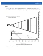
Page 146: ...in the symbol Figure A 3 RS309 30 Decode Zones In cm SE 1224 5 mil 4 25 8 00 7 5 mil 13 mil 3 75 13 50 26 75 41 50 72 00 20 mil 80 MRD 40 mil 86 25 55 mil Minimum distance determined by symbol length and scan angle W i d t h o f F i e l d Depth of Field Note Typical performance at 68 F 20 C on high quality symbols 2 75 2 25 4 00 5 75 0 5 10 15 5 10 15 20 25 20 25 0 12 7 25 4 38 1 12 7 25 4 38 1 50...

Page 147: ...00 30 50 70 75 20 mil 25 MRD 40 mil 86 00 55 mil Minimum distance determined by symbol length and scan angle W i d t h o f F i e l d Depth of Field Note Typical performance at 68 F 20 C on high quality symbols 3 25 2 00 3 25 4 50 0 5 10 15 5 10 15 20 25 20 25 0 12 7 25 4 38 1 12 7 25 4 38 1 50 8 63 5 50 8 63 5 100 UPC 70 177 8 65 165 1 60 152 4 55 139 7 50 127 0 45 114 3 40 101 6 35 88 9 30 76 2 2...

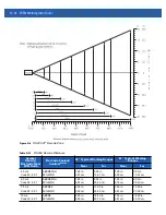
Page 148: ... 1 CD 80 MRD 5 75 in 14 6 cm Note 2 86 25 in 233 05 cm 4 50 in 11 43 cm Note 2 86 00 in 228 6 cm Table A 11 RS309 Decode Distances Continued Symbol Density Bar Code Type W N Ratio Bar Code Content ContrastNote 1 Typical 30 Working Ranges Typical 42 Working Ranges Near Far Near Far Notes 1 CONTRAST measured as Mean Reflective Difference MRD at 650 nm 2 Near ranges on lower densities are largely dep...

Page 149: ...ne for the RS409 The figures are typical values Table A 12 lists the typical distances for selected bar code densities The minimum element width or symbol density is the width in mils of the narrowest element bar or space in the symbol Figure A 5 RS409 35 Decode Zone ...

Page 150: ...ar Near Far 4 0 mil Code 39 2 5 1 ABCDEFGH 80 MRD 1 50 in 3 81 cm 5 50 in 13 97 cm 1 00 in 2 50 cm 5 50 in 13 97 cm 5 0 mil Code 39 2 5 1 ABCDEFGH 80 MRD 1 80 in 4 57 cm 8 00 in 20 32 cm 1 25 in 3 18 cm 8 00 in 20 32 cm 7 5 mil Code 39 2 5 1 ABCDEF 80 MRD 2 20 in 5 59 cm 13 00 in 33 02 cm 1 50 in 3 81 cm 13 00 in 33 02 cm 10 mil Code 39 2 5 1 ABCDE 90 MRD 2 20 in 5 59 cm 18 00 in 45 72 cm 1 50 in ...

Page 151: ...in 106 68 cm X 45 00 in 114 30 cm Notes 1 CONTRAST measured as Mean Reflective Difference MRD at 650 nm 2 Near ranges on lower densities not specified are largely dependent upon the width of the bar code and the scan angle 3 Working range specifications at ambient temperature 23 C Photographic quality symbols pitch 10 roll 0 skew 0 ambient light 150 ft candles 4 X Dependent on width of bar code 5 ...

Page 152: ...one for the RS419 The figures are typical values Table A 13 lists the typical distances for selected bar code densities The minimum element width or symbol density is the width in mils of the narrowest element bar or space in the symbol Figure A 7 RS419 Decode Zone ...

Page 153: ...n 4 06 cm 27 0 in 68 58 cm 15 mil Code 128 1234 80 MRD 1 0 in 2 54 cm Note 3 29 5 in 74 93 cm 20 mil Code 39 2 2 1 123 80 MRD 1 4 in 3 56 cm Note 3 52 0 in 132 08 cm 55 mil Code 39 2 2 1 CD 80 MRD 3 4 in 8 64 cm Note 3 100 0 in 254 00 cm 100 mil Code 39 3 0 1 reflective 123456 80 MRD 2 ft 60 96cm Note 3 17 ft 518 16 cm Notes 1 Contrast measured as Mean Reflective Difference MRD at 650 nm 2 Working...

Page 154: ...A 20 WT41N0 Integrator Guide ...

Page 155: ...s enabled A registry key on the wearable terminal can be modified to disable the StoneStreet One stack and enable the Microsoft stack Using a registry editor navigate to the following HKEY_LOCAL_MACHINE Software SymbolBluetooth Edit the following key SSStack dword 1 where 0 enable Microsoft stack and disable StoneStreet One stack default 1 enable StoneStreet One stack and disable Microsoft stack A...

Page 156: ...B 2 WT41N0 User Guide ...

Page 157: ...s phones medical and scientific equipment as well as Bluetooth devices all work within the 2 4 GHz ISM band 802 11g Similar to 802 11b but this standard supports signaling rates of up to 54Mbit sec It also operates in the heavily used 2 4 GHz ISM band but uses a different radio technology to boost overall throughput Compatible with the 802 11b A Access Point Provides a bridge between Ethernet wire...

Page 158: ... Second bps Bits transmitted or received Bluetooth A low cost short range radio link between two devices Bluetooth can replace cables and can be used to create ad hoc networks and provide a standard way to connect devices Bit Binary digit One bit is the basic unit of binary information Generally eight consecutive bits compose one byte of data The pattern of 0 and 1 values within the byte determine...

Page 159: ...d erases all user stored records and entries COM port Communication port ports are identified by number e g COM1 COM2 Continuous Code A bar code or symbol in which all spaces within the symbol are parts of characters There are no intercharacter gaps in a continuous code The absence of gaps allows for greater information density Cradle A cradle is used for charging the terminal battery and for comm...

Page 160: ...e pattern including start stop characters and data Encryption Encoding data to prevent it from being read by unauthorized people ENQ RS 232 ENQ software handshaking is also supported for the data sent to the host EMDK Enterprise Mobility Developer s Kit Ethernet An IEEE standard network protocol that specifies how data is placed on and retrieved from a common transmission medium ESD Electro Static...

Page 161: ...o a different network or subnetwork IP accepts packets from the layer 4 transport protocol TCP or UDP adds its own header to it and delivers a datagram to the layer 2 data link protocol It may also break the packet into fragments to support the maximum transmission unit MTU of the network IP Address Internet Protocol address The address of a computer attached to an IP network Every client and serv...

Page 162: ...er MDN Mobile Directory Number The directory listing telephone number that is dialed generally using POTS to reach a mobile unit The MDN is usually associated with a MIN in a cellular telephone in the US and Canada the MDN and MIN are the same value for voice cellular users International roaming considerations often result in the MDN being different from the MIN MIL 1 mil 1 thousandth of an inch M...

Page 163: ...at can have different values assigned to it PING Packet Internet Groper An Internet utility used to determine whether a particular IP address is online It is used to test and debug a network by sending out a packet and waiting for a response Programming Mode The state in which a scanner is configured for parameter values See Scanning Mode Q Quiet Zone A clear space containing no dark marks which p...

Page 164: ...r SSL uses the public and private key encryption system from RSA which also includes the use of a digital certificate Shared Key Shared Key authentication is an algorithm where both the AP and the MU share an authentication key Soft Reset See Warm Boot Specular Reflection The mirror like direct reflection of light from a surface which can cause difficulty decoding a bar code Subnet A subset of nod...

Page 165: ...ading firmware downloading software and remote booting of diskless devices TKIP Temporal Key Integrity Protocol A wireless encryption protocol that periodically changes the encryption key making it harder to decode Tolerance Allowable deviation from the nominal bar or space width Transmission Control Protocol Internet Protocol See TCP IP TLS Transport Layer Security TLS is a protocol that ensures ...

Page 166: ... protocol was specified in the IEEE 802 11 standard to provide a WLAN with a minimal level of security and privacy comparable to a typical wired LAN using data encryption WPA Wi Fi Protected Access is a data encryption specification for 802 11 wireless networks that replaces the weaker WEP It improves on WEP by using dynamic keys Extensible Authentication Protocol to secure network access and an e...

Page 167: ...th adaptive frequency hopping 6 1 bonding 6 18 deleting bonded device 6 21 discovering devices 6 9 6 31 turning off 6 4 6 7 6 30 turning on 6 4 6 7 6 30 Bluetooth printing 6 35 Bluetooth security 6 2 bonding bluetooth 6 18 boot cold 1 6 1 8 6 4 warm 1 8 6 4 BootLoader 7 5 error messages 7 13 bullets xiv C CAB files deployment via image update 7 8 changing the power settings 1 9 charging spare batt...

Page 168: ...titions 7 3 copyfile 7 4 regmerge 7 3 flash storage 7 3 four slot Ethernet cradle 2 6 2 17 drivers 2 10 four slot Ethernet USB 2 1 four slot spare battery charger 2 1 2 19 G getting started 1 3 H hard reset 1 6 1 8 6 4 humidity A 2 A 4 A 5 A 7 I image update deploying CAB files 7 8 information service xv installation development tools 7 3 installing main battery 1 3 Installing Window Mobile Device...

Page 169: ... 7 9 7 12 spare batteries charging 1 5 spare battery charging 1 5 spare battery charger 2 13 power connection 2 13 splash screen 7 5 creating 7 16 starting the wearable terminal 1 3 1 6 storage temperature A 2 A 3 A 4 A 5 A 7 suspend 1 5 6 5 Syncing Installing ActiveSync 3 1 Windows Mobile Device Center 3 3 T technical specifications wearable terminal A 1 temperature battery charging A 8 troublesh...

Page 170: ...Index 4 WT41N0 Integrator Guide ...

Page 171: ......

Page 172: ...TOROLA MOTO MOTOROLA SOLUTIONS and the Stylized M Logo are trademarks or registered trademarks of Motorola Trademark Holdings LLC and are used under license All other trademarks are the property of their respective owners 2012 Motorola Solutions Inc All Rights Reserved 72E 160600 01 Revision A December 2012 ...

Reviews: