6 Installation Instructions
34
Rev. 02/2018
2.
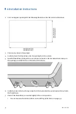
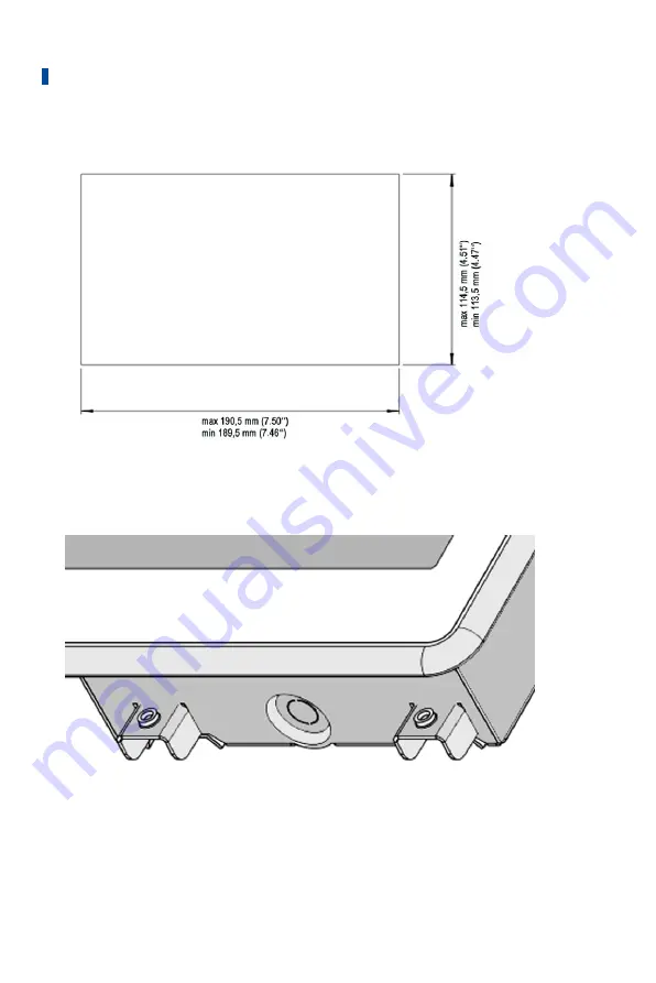
Cut a rectangular opening with the following dimensions into the control cabinet door:
3.
If necessary, remove sharp edges.
4.
Carefully insert the PowerView3 into the opening from the outside.
5.
Hold the PowerView3 firmly while a second person hooks in the four attachment clamps in
the openings provided for this on the sides of the device.
6.
Carefully screw in the four fixing screws from the back while the second person firmly holds
the PowerView3.
7.
Check if the PowerView3 is mounted tightly in the correct position.
▸
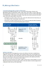
You can now wire the device (refer to section
Wiring of the Device
on page 35).
Summary of Contents for PoewerView3
Page 1: ...PowerView3 HMI Module Operating Manual P N 01 10 015 EN Rev 02 2018...
Page 16: ...4 Product Description 16 Rev 02 2018...
Page 17: ...4 Product Description Rev 02 2018 17...
Page 18: ...4 Product Description 18 Rev 02 2018...
Page 19: ...4 Product Description Rev 02 2018 19...
Page 26: ...4 Product Description 26 Rev 02 2018 4 1 8 Overview Drawings Rear View...
Page 27: ...4 Product Description Rev 02 2018 27 Plan View Side View...
Page 137: ...Rev 02 2018 137...
Page 138: ......

