Rev. 02/2018
35
Use in potentially explosive atmospheres
For use in a hazardous area of Class I, Division 2, Groups C and D, T4 in the
USA and Canada, it is imperative that you observe the information of the
CSA Certificate 2173514 (see section
Certifications
on page 15) for the
PowerView3.
The PowerView3 must be securely mounted in a control cabinet before wiring (see section
Installation
on page 33).
7.1
CAN Bus Wiring
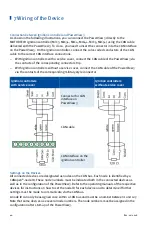
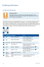
All devices are connected to the PowerView3 via a CAN bus. The communication via the bus is
effected using the CANopen
®
protocol with a bit rate of 250 kbit/s.
General Information on CAN Bus Wiring
The wiring of the CAN bus requires three conductors (CAN Hi, CAN Lo and CAN Com). The
conductors for CAN Hi and CAN Lo must be twisted wires. At a bit rate of 250 kbit/s, the bus may
only have a maximum wire length of 250 m (820') and must be terminated at both ends by a
terminating resistor of 120 Ω between the CAN Hi and CAN Lo conductors to prevent reflections.
7 Wiring of the Device
Summary of Contents for PoewerView3
Page 1: ...PowerView3 HMI Module Operating Manual P N 01 10 015 EN Rev 02 2018...
Page 16: ...4 Product Description 16 Rev 02 2018...
Page 17: ...4 Product Description Rev 02 2018 17...
Page 18: ...4 Product Description 18 Rev 02 2018...
Page 19: ...4 Product Description Rev 02 2018 19...
Page 26: ...4 Product Description 26 Rev 02 2018 4 1 8 Overview Drawings Rear View...
Page 27: ...4 Product Description Rev 02 2018 27 Plan View Side View...
Page 137: ...Rev 02 2018 137...
Page 138: ......

