VMX-Synergy
™
Plus
–
ANSI - Quick Start Guide
19 |
P a g e
Wiring Connection
The programmed digital input voltage settings match the voltage applied to these terminals to
avoid risk of damage to the equipment.
The control supply can be 120 to 240Vac applied to the N, L terminals. Check model number to
determine correct control supply voltage (240AC is optional) to avoid risk of damage to the
equipment.
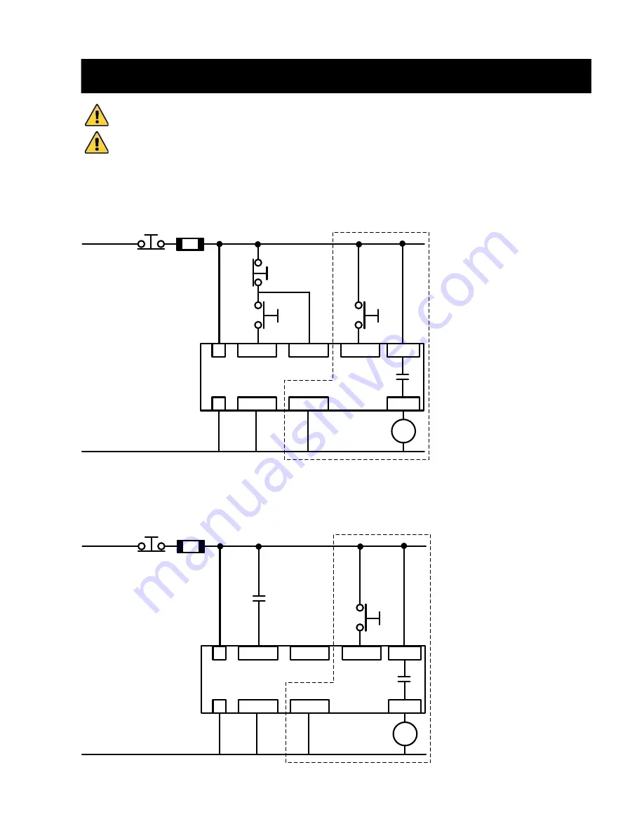
Three Wire Control
3 Wire Control Diagram 120VAC control supply and digital input programming.
L
N
DI1
DI1/2COM
DI2
DI3/4COM
DI3
DO5NO
DO5COM
FU1
EMERGENCY
STOP
120VAC
STOP
START
RESET
K1
N
(OPTIONAL)
LINE ISOLATION
CONTACTOR
(240V OPTIONAL)
OPTIONAL
Two Wire Control
2 Wire Control Diagram 120VAC control supply and digital input programming.
L
N
DI1
DI1/2COM
DI2
DI3/4COM
DI3
DO5NO
DO5COM
FU1
EMERGENCY
STOP
120VAC
RUN
COMMAND
CONTACT
RESET
K1
N
(OPTIONAL)
LINE ISOLATION
CONTACTOR
(240V OPTIONAL)
OPTIONAL
Summary of Contents for VMX-Synergy Plus ANSI
Page 1: ......
Page 26: ...VMX Synergy Plus ANSI Quick Start Guide 26 P a g e Monitor ...
Page 35: ......


