background image


Manual #100-7100 


16 

Use with adequate ventilation.  Avoid breathing vapors. 

Improper use of service fluid can cause injury. 
Over exposure can have harmful effect on eyes, skin, respiratory system and possible 
unconsciousness and asphyxiation. 

Improperly blocked vehicles can move. 

Set the parking brake and chock the wheels. 

Moving vehicles can cause injury. 

Moving engine parts. 
The engine cooling fan will cycle on and off depending on the coolant temperature and could 
operate without the engine running. 

Wear safety goggles. 
Always keep objects, clothing, and hands away from the cooling fans and engine parts. 

Moving engine parts can cause injury. 

Hot surfaces are present during and after running the engine. 

Do not contact hot surfaces such as, manifolds, pipes, mufflers, catalytic converters, or 
radiators and hoses. 

Hot surfaces can cause injury. 

Catalytic converters become extremely hot. 

Do not park a converter-equipped vehicle over dry grass, leaves, paper, or any other 
flammable material. 
Do not touch a catalytic converter until the engine has been off for at least 45 minutes. 

Catalytic converters can cause burns. 
 

Cracked fan blade can become airborne. 

Examine fan blades for cracks.  If found, do not service the vehicle. 

Flying objects can cause injury. 

 
Batteries produce explosive gases and can explode, resulting in injury. 

Wear safety goggles when working on or near batteries. 
Use in a well-ventilated area. 
Keep sparks and flames away from the battery and never lay tools, equipment, or other 
conductive objects on the battery. 
When is connecting to the battery, make sure the unit’s power switch is off.  Connect the 
positive lead of the unit to the positive lead battery first; connect the negative lead of the 
unit to a solid ground point as far from the battery as possible. 
Keep battery acid away from skin or eyes.  In case of eye contact, flush with clean water 
for 15 minutes and get medical attention. 
 

Always use a fender cover when working under the hood, to protect vehicles finish. 

Rinse any spills with water immediately. 

Summary of Contents for SteerClean-II 500-7100

Page 1: ...MPS 7100 STEERCLEAN II Manual P N 100 7100 Rev A 2006 MOTORVAC TECHNOLOGIES INC SteerClean II Power Steering Service System Operator Manual MODEL 500 7100...

Page 2: ...Manual 100 7100 ii...

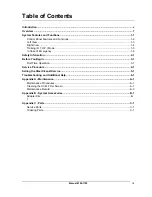
Page 3: ...mergency 1 6 Safety Information 2 1 Before You Begin 3 1 First Time Operation 3 1 Service Procedure 4 1 Selling the SteerClean II Service 5 1 Troubleshooting and Additional Help 6 1 Appendix A Mainten...

Page 4: ...Manual 100 7100 iv Notes...

Page 5: ...ur shop with over 30 000 miles is a potential customer This service is also recommended every two years But the key to profit is to sell the service so we have included a detailed sales procedure at t...

Page 6: ...Manual 100 7100 vi Notes...

Page 7: ...times Before You Begin Follow the instructions in this chapter before using the unit for the first time Service Procedure This chapter contains step by step setup and service procedure for using the...

Page 8: ...Manual 100 7100 8 Notes...

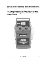
Page 9: ...Manual 100 7100 9 System Features and Functions The front of the MotorVac SteerClean II cabinet showing the control panel waste hose service hoses and sink...

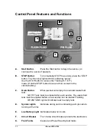
Page 10: ...n connect to the vehicle battery C Drain Button When pushed will empty the on board waste fluid tank NOTE Tank must be emptied after each service The waste fluid tank must be emptied before a new serv...

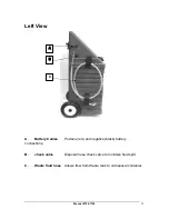
Page 11: ...eft View A Battery Cables Positive red and negative black battery connections B check valve Disposal hose check valve to minimize fluid spill C Waste fluid hose Allows flow from Waste tank to oil disp...

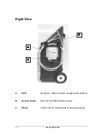
Page 12: ...Manual 100 7100 12 Right View A Sink Stores the wand and acts as waste tank overflow B Service Hoses New and used fluid delivery hoses C Wand Inserts into the vehicles power steering reservoir A B C...

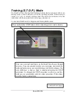
Page 13: ...nter the S T O P mode for Supplemental Training On Premises continued next page Now you can watch and listen as the SteerClean II goes through its paces You can actually hear the voice prompts and wat...

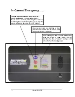
Page 14: ...ce or something happens that requires you to stop the service momentarily press the STOP button After pushing the STOP button the Running light will begin to blink telling you the machine has been pau...

Page 15: ...engine can ignite Avoid exposure to flames sparks hot engine parts and other ignition sources Always keep fully charge fire extinguisher nearby The extinguisher should have a class B rating and be sui...

Page 16: ...pped vehicle over dry grass leaves paper or any other flammable material Do not touch a catalytic converter until the engine has been off for at least 45 minutes Catalytic converters can cause burns C...

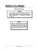
Page 17: ...after receiving inspection of the unit Operate in above 50 degrees Fahrenheit area Remember to send in your warranty card NOTE Check the output return hoses battery connections and all external compo...

Page 18: ...Manual 100 7100 18 Notes...

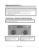
Page 19: ...g Fluid For most vehicles this is as simple as one two three 1 Connect unit to the vehicles battery 2 Install the unit s wand into the vehicles power steering reservoir 3 Push the start button Here is...

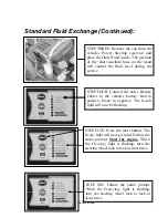
Page 20: ...w go solid Follow the audio prompt Start the engine When the Cleaning light is flashing turn the steering wheel lock to lock at least twice STEP THREE Remove the cap from the vehicles Power Steering r...

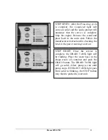
Page 21: ...units sink Follow the manufactures instruction for checking the level in the power steering reservoir STEP EIGHT Once the service is complete the DRAIN TANK light will be flashing Place the waste hose...

Page 22: ...Manual 100 7100 22 Notes...

Page 23: ...cost effective way to replace power steering fluid With the MotorVac SteerClean II System you actually introduce a cleaning agent first SC7 Flush Detergent and then flush the system completely with Mo...

Page 24: ...Always answer any questions as truthfully as possible and then always come back to the sales question Can we take care of that for you now Once his objectives have been satisfied you have good chance...

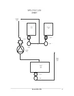
Page 25: ...ween the pump and the waste tank To access remove the front lower metal cover The filter and pump are located in the space below the waste capture tank Clamp the hose closed between filter and tank Pu...

Page 26: ...Manual 100 7100 26 714 558 4822 MotorVac distirbutor...

Page 27: ...Manual 100 7100 27...

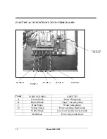
Page 28: ...OLORS GOES TO A Green black flush fluid pump B Brown black large vacuum pump C Blue black Waste tank pump D Yellow black Power steering fluid pump White black Low level switch in waste tank Red black...

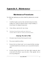
Page 29: ...rays 3 Clean the unit s waste filter screen after every 100 services or 6 months which ever comes first See the next section for procedure Cleaning The Unit s Filter 1 Disconnect power harness from an...

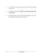
Page 30: ...o pull screen away from the filter housing Clean screen 6 Assemble in reverse order NOTE Use caution not to pinch o ring on reassembly 7 Enter initials date and a check mark in the appropriate boxes o...

Page 31: ...t lead to the external hose fittings 3 disconnect wiring connectors to pumps 4 remove sub assembly from cabinet 5 disconnect hose from bottom tank fitting 6 remove bottom tank fitting 7 use a pick to...

Page 32: ...32 Maintenance Record Use the following table to keep a record of maintenance performed on the unit Initial Date DRAIN WASTE TANK 9 CLEANED FILTER 9 CLEAN EXT CABINET 9 CHECK HOSES AND WIRES 9 OTHER...

Page 33: ...Manual 100 7100 33 Standard Adapters...

Page 34: ...k Nylon 010 5500 Axle Rear Wheels x 20 875 lg 010 5004 Hose bracket 200 7111 Control panel assembly with Printed Circuit Board 020 5341 VERSION 2 PROM Printed Circuit Board 020 8043 Harness External P...

Page 35: ...s 2 B 070 0090 Hose sold by the foot C 030 4013 female T fitting 1 D 050 3009 1 lb check valve 2 E 050 2406 Pump 2 F 030 4410 Elbow fitting TB x 3 8 MCT for Suction pump 2 G 050 2400 Vacuum pump 1 H 0...

Page 36: ...050 1000 FILTER 1 F 030 4007 90 DEGREE ELBOW WING NUT TO BARB 1 G 070 0090 HOSE CLEAR BRAIDED H 010 7101 TANK 1 I 050 2700 LOW LEVEL SWITCH 1 J 030 4410 ELBOW NY TO 3 8 MPT 2 ORDERING PARTS Parts for...

Page 37: ...Manual 100 7100 37...
Reviews: