Pa
g
.
1
1
11
-
M
a
n
u
a
l c
o
d
e:
1
1
9
R
7
1
7
9
G
B
11
9
R
7
1
7
9
G
B
ve
r.
3
.0
3.
0
0
7
/2
0
0
9
- T
h
e d
a
ta a
n
d i
n
fo
rm
ati
o
n i
n
th
is
m
a
n
u
a
l a
re s
u
b
je
ct t
o
c
h
a
n
g
e
at a
n
y ti
m
e
.
4
- Secure the curved arm to the
head bracket using the supplied
screw and nut. Lubricate it and check
that the arm rotates freely.
5
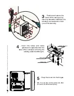
- Perforate the cable feedthrough
to the base bracket on the side of
the cable gland.
6
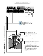
- Insert the cable into the
cable gland and block it.
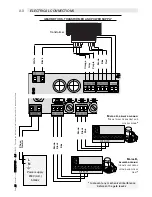
Connect the gearmotor cables
to the power cables coming
from the control panel (see
diagram on page 22).
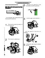
SECURING THE GEARMOTOR


