Pa
g
.
2
2
22
- M
a
n
u
a
l c
o
d
e:
1
1
9
R
7
1
7
9
G
B
11
9
R
7
1
7
9
G
B
ve
r.
3
.0
3.
0
0
7
/2
0
0
9 - T
h
e d
a
ta a
n
d i
n
fo
rm
ati
o
n i
n
th
is
m
a
n
u
a
l a
re s
u
b
je
ct t
o
c
h
a
n
g
e
at a
n
y ti
m
e
.
3.2
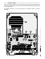
CONTROL BOARD AND ITS FUNCTIONS – DESCRIPTION
The control panel should be powered
with 230V A.C., with max 50/60Hz fre-
quency.
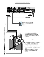
The command devices and accesso-
ries are rated at 24V (N.B. The overall
power draw from the connected acces-
sories must not exceed 37W).
The card is fi tted with an amperometric
device which constantly monitors the
motor’s thrust rate.
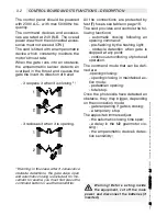
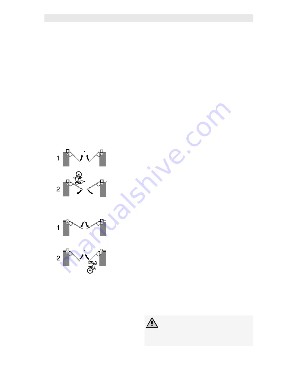
When the gate runs into an obstacle,
the amperometric sensor detects an
overload in the thrust and causes the
gate the invert its direction of travel:
- it reopens it when it is closing
(1)
;
- it recloses it when it is opening.
(1)
Warning: in this case, after 3 consecutive
obstacle detections, the gate stays open
and automatic closing is excluded; for mo-
vement to resume, you must fi rst press the
command button or use the transmitter.
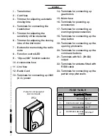
All the connections are protected by
fast (F) fuses, see table on page 19.
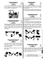
The card provides and controls the fol-
lowing functions:
- automatic closing following an
opening command;
- pre-fl ashing by the fl ashing light;
- obstacle detection when gate is
stopped at any point;
- continuous monitoring of photocell
operation.
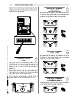
The command mode that can be defi -
ned are:
-opening/closing;
- opening/closing in maintained ac-
tion mode;
- pedestrian opening;
- total stop.
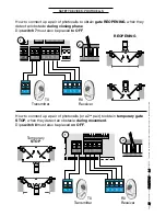
Once the photocells have detected an
obstacle, they may trigger, depending
on the connection mode:
- gate reopening if gate is closing;
- a temporary stop.
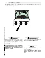
The apposite trimmers adjust:
- the automatic closing time span;
- a delay in the M2 gearmotor clo-
sing ;
- the amperometric device’s detec-
tion sensitivity;
Warning! Before acting inside
the equipment, cut off the main
power and disconnect the batteries (if
inserted).


