background image

Pa

g

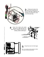
3

5

35

  - 

M

a

n

u

a

l c

o

d

e: 

1

1

9

R

7

1

7

9

G

B

11

9

R

7

1

7

9

G

B

 ve

r.


3

.0

3.

0

  0

7

/2

0

0

9

  - T

h

e d

a

ta a

n

d i

n

fo

rm

ati

o

n i

n

 th

is

 m

a

n

u

a

l a

re s

u

b

je

ct t

o

 c

h

a

n

g

e

 at a

n

y ti

m

e

.

Extraordinary maintenance log:

 the following tables are for logging any extraordinary maintenance actions, 

repairs or changes made to the system, when performed by qualified firms/staff, as required by current law.

Installer/maintenance staff stamp

Date of intervention

Name of Installer/maintenance staffer

Signature of owner 

Signature of Installer/maintenance staffer

Type of intervention ____________________________________________________________________________________
_________________________________________________________________________________________________
_________________________________________________________________________________________________

Date  User’s_signature
Notes


Date  User’s_signature
Notes

- _ _ _ _ _ _ _ _ _ _ _ _ _ _ _ - _ _ _ _ _ _ _ _ _ _ _ _ _ _ _ _ _ _ _ _ _ _

- _ _ _ _ _ _ _ _ _ _ _ _ _ _ _ _ _ _ _ _ _ _ _ _ _ _ _ _ _ _ _ _ _ _ _ _ _

- _ _ _ _ _ _ _ _ _ _ _ _ _ _ _ - _ _ _ _ _ _ _ _ _ _ _ _ _ _ _ _ _ _ _ _ _ _

- _ _ _ _ _ _ _ _ _ _ _ _ _ _ _ _ _ _ _ _ _ _ _ _ _ _ _ _ _ _ _ _ _ _ _ _ _

- _ _ _ _ _ _ _ _ _ _ _ _ _ _ _ - _ _ _ _ _ _ _ _ _ _ _ _ _ _ _ _ _ _ _ _ _ _

- _ _ _ _ _ _ _ _ _ _ _ _ _ _ _ _ _ _ _ _ _ _ _ _ _ _ _ _ _ _ _ _ _ _ _ _ _

- _ _ _ _ _ _ _ _ _ _ _ _ _ _ _ - _ _ _ _ _ _ _ _ _ _ _ _ _ _ _ _ _ _ _ _ _ _

- _ _ _ _ _ _ _ _ _ _ _ _ _ _ _ _ _ _ _ _ _ _ _ _ _ _ _ _ _ _ _ _ _ _ _ _ _

- _ _ _ _ _ _ _ _ _ _ _ _ _ _ _ - _ _ _ _ _ _ _ _ _ _ _ _ _ _ _ _ _ _ _ _ _ _

- _ _ _ _ _ _ _ _ _ _ _ _ _ _ _ _ _ _ _ _ _ _ _ _ _ _ _ _ _ _ _ _ _ _ _ _ _

- _ _ _ _ _ _ _ _ _ _ _ _ _ _ _ - _ _ _ _ _ _ _ _ _ _ _ _ _ _ _ _ _ _ _ _ _ _

- _ _ _ _ _ _ _ _ _ _ _ _ _ _ _ _ _ _ _ _ _ _ _ _ _ _ _ _ _ _ _ _ _ _ _ _ _

- _ _ _ _ _ _ _ _ _ _ _ _ _ _ _ - _ _ _ _ _ _ _ _ _ _ _ _ _ _ _ _ _ _ _ _ _ _

- _ _ _ _ _ _ _ _ _ _ _ _ _ _ _ _ _ _ _ _ _ _ _ _ _ _ _ _ _ _ _ _ _ _ _ _ _

- _ _ _ _ _ _ _ _ _ _ _ _ _ _ _ - _ _ _ _ _ _ _ _ _ _ _ _ _ _ _ _ _ _ _ _ _ _

- _ _ _ _ _ _ _ _ _ _ _ _ _ _ _ _ _ _ _ _ _ _ _ _ _ _ _ _ _ _ _ _ _ _ _ _ _

- _ _ _ _ _ _ _ _ _ _ _ _ _ _ _ - _ _ _ _ _ _ _ _ _ _ _ _ _ _ _ _ _ _ _ _ _ _

- _ _ _ _ _ _ _ _ _ _ _ _ _ _ _ _ _ _ _ _ _ _ _ _ _ _ _ _ _ _ _ _ _ _ _ _ _

- _ _ _ _ _ _ _ _ _ _ _ _ _ _ _ - _ _ _ _ _ _ _ _ _ _ _ _ _ _ _ _ _ _ _ _ _ _

- _ _ _ _ _ _ _ _ _ _ _ _ _ _ _ _ _ _ _ _ _ _ _ _ _ _ _ _ _ _ _ _ _ _ _ _ _

- _ _ _ _ _ _ _ _ _ _ _ _ _ _ _ - _ _ _ _ _ _ _ _ _ _ _ _ _ _ _ _ _ _ _ _ _ _

- _ _ _ _ _ _ _ _ _ _ _ _ _ _ _ _ _ _ _ _ _ _ _ _ _ _ _ _ _ _ _ _ _ _ _ _ _

- _ _ _ _ _ _ _ _ _ _ _ _ _ _ _ - _ _ _ _ _ _ _ _ _ _ _ _ _ _ _ _ _ _ _ _ _ _

- _ _ _ _ _ _ _ _ _ _ _ _ _ _ _ _ _ _ _ _ _ _ _ _ _ _ _ _ _ _ _ _ _ _ _ _ _

- _ _ _ _ _ _ _ _ _ _ _ _ _ _ _ - _ _ _ _ _ _ _ _ _ _ _ _ _ _ _ _ _ _ _ _ _ _

- _ _ _ _ _ _ _ _ _ _ _ _ _ _ _ _ _ _ _ _ _ _ _ _ _ _ _ _ _ _ _ _ _ _ _ _ _

- _ _ _ _ _ _ _ _ _ _ _ _ _ _ _ - _ _ _ _ _ _ _ _ _ _ _ _ _ _ _ _ _ _ _ _ _ _

- _ _ _ _ _ _ _ _ _ _ _ _ _ _ _ _ _ _ _ _ _ _ _ _ _ _ _ _ _ _ _ _ _ _ _ _ _

- _ _ _ _ _ _ _ _ _ _ _ _ _ _ _ - _ _ _ _ _ _ _ _ _ _ _ _ _ _ _ _ _ _ _ _ _ _

- _ _ _ _ _ _ _ _ _ _ _ _ _ _ _ _ _ _ _ _ _ _ _ _ _ _ _ _ _ _ _ _ _ _ _ _ _

- _ _ _ _ _ _ _ _ _ _ _ _ _ _ _ - _ _ _ _ _ _ _ _ _ _ _ _ _ _ _ _ _ _ _ _ _ _

- _ _ _ _ _ _ _ _ _ _ _ _ _ _ _ _ _ _ _ _ _ _ _ _ _ _ _ _ _ _ _ _ _ _ _ _ _

- _ _ _ _ _ _ _ _ _ _ _ _ _ _ _ - _ _ _ _ _ _ _ _ _ _ _ _ _ _ _ _ _ _ _ _ _ _

- _ _ _ _ _ _ _ _ _ _ _ _ _ _ _ _ _ _ _ _ _ _ _ _ _ _ _ _ _ _ _ _ _ _ _ _ _

- _ _ _ _ _ _ _ _ _ _ _ _ _ _ _ - _ _ _ _ _ _ _ _ _ _ _ _ _ _ _ _ _ _ _ _ _ _

- _ _ _ _ _ _ _ _ _ _ _ _ _ _ _ _ _ _ _ _ _ _ _ _ _ _ _ _ _ _ _ _ _ _ _ _ _

- _ _ _ _ _ _ _ _ _ _ _ _ _ _ _ - _ _ _ _ _ _ _ _ _ _ _ _ _ _ _ _ _ _ _ _ _ _

- _ _ _ _ _ _ _ _ _ _ _ _ _ _ _ _ _ _ _ _ _ _ _ _ _ _ _ _ _ _ _ _ _ _ _ _ _

- _ _ _ _ _ _ _ _ _ _ _ _ _ _ _ - _ _ _ _ _ _ _ _ _ _ _ _ _ _ _ _ _ _ _ _ _ _

- _ _ _ _ _ _ _ _ _ _ _ _ _ _ _ _ _ _ _ _ _ _ _ _ _ _ _ _ _ _ _ _ _ _ _ _ _

Periodic maintenance log:

 table for logging any actions performed by the user (see page 34); we suggest 

performing an inspection every six months.

MAINTENANCE LOGS

Installer/maintenance staff stamp

Date of intervention

Name of Installer/maintenance staffer

Signature of owner 

Signature of Installer/maintenance staffer

Type of intervention ____________________________________________________________________________________
_________________________________________________________________________________________________
_________________________________________________________________________________________________
Installer/maintenance staff stamp

Date of intervention

Name of Installer/maintenance staffer

Signature of owner 

Signature of Installer/maintenance staffer

Type of intervention ____________________________________________________________________________________
_________________________________________________________________________________________________
_________________________________________________________________________________________________
Summary of Contents for ECLISTAR

Page 1: ...ECLISTAR SWING GATE OPERATOR INSTALLATION MANUAL ...

Page 2: ...ing the radio code pag 31 3 8 Control LEDs functions pag 32 3 9 Final operations pag 32 4 0 Warnings and precautions pag 33 5 0 Troubleshooting pag 33 6 0 Maintenance pag 34 7 0 Dismissal and disposal pag 36 1 0 GENERAL CHARACTERISTICS Operator for swing gates up to 2 20 m per gate leaf 230V A C powered IP54 protection rating fitted with autoapprendimento del codice tra trasmettitore e ricevitore r...

Page 3: ...ews 6 Transmission arms 7 Cable feedthroughs 8 Cable gland 1 2 TECHNICAL CHARACTERISTICS 24V D C self locking gearmotor powered by a 230V A C control panel 1 3 DIMENSIONS Power supply to control panel 230V A C 50 60Hz Power supply to gearmotor 24V D C Max power 140W Nominal supply voltage 5A max Max thrust 180N Max frequency of use 45 cycles h Duty cycle 50 Reduction ratio 1 36 Operating temperatu...

Page 4: ... built in antenna 2 Keypad selector 3 Control panel 4 Photocell 5 Junction box for passage of electrical cables 6 Gearmotors 7 Transmitters The standard installation shown is only an example Check the illustrations and the contents list in the kit box you have purchased Number of wires per cable section Ⓐ Ⓐ Ⓑ Ⓑ Ⓐ Power supply 3 x 1 5 Ⓑ RX photocell 4 x 0 5 Ⓒ TX photocell 2 x 0 5 Ⓓ flashing light 2 ...

Page 5: ... 5 1 2 4 6 7 Ⓐ Ⓐ Ⓒ Ⓔ Ⓒ Ⓔ Ⓒ Ⓒ Ⓓ Ⓕ Ⓓ Ⓕ Ⓐ Ⓑ Ⓒ Ⓐ Ⓑ Ⓒ Ⓓ Ⓔ Ⓕ Ⓓ Ⓔ Ⓕ The data and information in this manual are subject to change at any time and without need of prior notice 119R7179GB 119R7179GB ver 3 0 3 0 07 2009 Pag 5 ...

Page 6: ...ation in this manual are subject to change at any time 1 5 LIMITS TO USE Opening angle A B C 90 140 205 0 50 430 140 195 75 100 430 140 185 125 150 400 140 175 175 200 400 110 180 210 0 430 200 205 50 430 The maximum width of the gate leaf must not exceed 2 2 metres and its max weight cannot exceed 300 kg ...

Page 7: ...ct to change at any time 2 0 INSTALLING THE AUTOMATION GATE CHECKS BEFORE INSTALLING Check that the gate structure is sturdy and that the hinges are in proper condition Make sure that there is a closing and opening mechanical door endstop that is well secured to the ground to prevent over run of the gate leaf ...

Page 8: ...nd junction boxes 3 Decide where to fix the head bracket Position the base plate on the post making sure the fixing and application measurements are right see this drawing see page 6 2 Insert the electrical cables that come from the junction pit into the tubes making sure the sections are right depending on the use to be made see installation on page 4 PRELIMINARY OPERATIONS AND BRACKET MOUNTING Hea...

Page 9: ... the axis of the hinge while taking into account the A and B measurements as shown in the table on page 6 7 Secure the bracket using securing elements chosen according to the gate type and materials 4 Secure the base plate using securing elements chosen according to the post type and materials PRELIMINARY OPERATIONS AND BRACKET MOUNTING 5 Insert the cable feedthroughs and the cable gland into the ...

Page 10: ...g the supplied screws and nuts Warning a sticker tag on the microswitch shows whether that gearmotor should be mounted to the right DX or to the left SX 2 Insert and secure the straight arm into the gearmotor shaft using plug screw and relative bushing Lubricate the bushing insert it into the straight arm and join it to the curved arm using the supplied screw the washers and nut 3 R e l e a s e t ...

Page 11: ...o the head bracket using the supplied screw and nut Lubricate it and check that the arm rotates freely 5 Perforate the cable feedthrough to the base bracket on the side of the cable gland 6 Insert the cable into the cable gland and block it Connect the gearmotor cables to the power cables coming from the control panel see diagram on page 22 SECURING THE GEARMOTOR ...

Page 12: ...ace the gate leaf at a distance of 5 cm from the opening endstop ADJUSTING THE ENDSTOPS LEFT HAND GEARMOTOR INNER VIEW until the microswitch is activated 2 Rotate the lower cam clockwise ADJUSTING THE OPENING ENDSTOP 3 Secure the cam using the central screw Opening microswitch Lower cam Closing microswitch Upper cam Upper cam securing screw Lower cam securing screw ...

Page 13: ...lease the gearmotor and completely close the gate leaf 2 Rotate the upper cam counter clockwise 3 Secure the cam using the lateral screws N B Always adjust the opening endstop before adjusting the closing one until the switch of the micro is released Warning the upper cam of the operator s endstop assembly is set up for gate leaf widths ranging from 1 20 m to 2 20 m ADJUSTING THE ENDSTOPS ...

Page 14: ... the lateral screws 2 Turn the cam upside down 3 Release the gearmotor and completely close the gate leaf 4 Turn the upper cam counter clockwise until the switch of the micro is released N B If the gate leaf measures less than N B If the gate leaf measures less than 1 20 metres 1 20 metres turn the upper cam upside down and then adjust the endstop 1 Remove the securing screws from the upper cam AD...

Page 15: ...ing microswitch Lower cam Closing microswitch Upper cam Upper cam securing screw Lower cam securing screw 1 With the motor released place the gate leaf at a distance of 5 cm from the opening endstop until the switch of the micro is activated 2 Rotate the lower cam counter clockwise ADJUSTING THE ENDSTOPS 3 Secure the cam using the central screw ADJUSTING THE OPENING ENDSTOP ...

Page 16: ...s released 2 Rotate the upper cam clockwise 3 Secure the cam using the lateral screws 1 Release the gearmotor and completely close the gate leaf N B Always adjust the opening endstop before adjusting the closing one Warning the upper cam of the operator s endstop assembly is set up for gate leaf widths ranging from 1 20 m to 2 20 m ADJUSTING THE ENDSTOPS ADJUSTING THE CLOSING ENDSTOP ...

Page 17: ...ure less than 1 2 metres 1 2 metres turn the upper cam upside down and then adjust the endstop 5 Secure the cam using the lateral screws 2 Turn the cam upside down 3 Release the gearmotor and completely close the gate leaf 4 turn the upper cam clockwise until the switch of the micro is released 1 Remove the securing screws of the upper cam ADJUSTING THE ENDSTOPS continue adjusts the right hand clo...

Page 18: ...s manual are subject to change at any time 3 0 CONTROL PANEL Il The control panel is made up of a two colour ABS casing featuring a fully opening hatch which can be hinged either right or left Inside the control board featuring a receiver radio card and transformer We suggest installing it in an area protected from accidental impacts or possible tampering ...

Page 19: ...io Card 13 Terminals for connecting up 230V A C power 14 Terminals for connecting up gearmotors 15 Motor fuse 16 Terminals for powering up accessories 17 Terminals for connecting up warning signal accessories 18 Terminals for connecting up the stop button 19 Terminals for connecting up the opening photocells 20 Terminals for connecting up the command buttons 21 Terminals with N O B1 B2 output 22 T...

Page 20: ...nges 2 Insert the hinges into the base of the casing either right or left as you prefer and secure them using the supplied screws and washers They slide to rotate 3 1 ASSEMBLING AND SECURING THE CASING Before securing the casing to the wall you need to assemble and mount the hinges on the side you prefer N B you may also just wish to secure the cover using the 4 screws ...

Page 21: ...e of the casing using securing elements suitable to the structure and surface to which you will be securing 4 Insert the tubes and cable glands not supplied under the base of the container removing the existing cable feedthroughs cable gland 5 Snap the cover into the hinges N B You can also do this at the end after you have connected everything Cables tube cable feedthrough ...

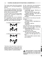
Page 22: ...the gate stays open and automatic closing is excluded for mo vement to resume you must first press the command button or use the transmitter All the connections are protected by fast F fuses see table on page 19 The card provides and controls the fol lowing functions automatic closing following an opening command pre flashing by the flashing light obstacle detection when gate is stopped at any point ...

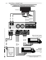
Page 23: ...ower supply 230V A C 50 60z MOTOR A DELAYED CLOSING THE GATE LEAF OPENS FIRST AND CLOSES SECOND MOTOR B DELAYED OPENING THE GATE LEAF OPENS SECOND AND CLOSES FIRST Transformer Phase Neutral Brown Black Blue Brown Black Blue White Black Orange Grey Purple Brown Blue Red to prevent any mechanical interference between the gate leaves GEARMOTORS TRANSFORMER AND POWER SUPPLY ...

Page 24: ...g cycle To resume movement press the command or transmitter button Terminals for powering up 24V a c d c accessories for a max total of 4W N O contact for Command buttons for C Pedestrian Opening opens only one gate leaf for persons to pass or with dip switch 6 ON for D Opening in Maintained Action Mode N O contact for Command button for A Opening and Closing the gate see dip switch 2 for which mo...

Page 25: ...ement and pre flashing mode can also be selected OR 24V 25W cycle lamp which stays on during the entire opening and closing cycles Automatic Closing and Obstacle Detection functions must be activated see pages 27 and 28 N B For this option you need to connect up antenna item code OA533 Warning light 24V 3W It stays on to signal that gate is open WARNING AND LIGHTING DEVICES RG58 cable Sock ...

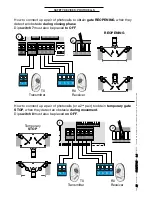
Page 26: ...nge at any time SAFETY DEVICES PHOTOCELLS How to connect up a pair of photocells to obtain gate REOPENING when they detect an obstacle during closing phase Dip switch 7 must also be placed to OFF TX Transmitter RX Receiver TX Transmitter RX Receiver How to connect up a pair of photocells or a 2nd pair to obtain temporary gate STOP when they detect an obstacle during movement Dip switch 8 must also...

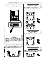
Page 27: ...r described on page 29 Automatic closing may be interrupted by a command from a button by the transmitter or by the action of the photocells This function deactivates anyhow after a STOP action or when the power is out SEQUENTIAL COMMAND 2 ON 3 OFF By pressing the button connected on G Ps or that on the transmitter the command se quence will be Open Stop Close Stop STEP STEP COMMAND 2 OFF 3 OFF By...

Page 28: ...page 26 If there are no photocells or other safety devi ces connected leave the dip switches ON Press the button or use the transmitter for the gate to move again If you have also selected automatic closing dip switch 1 ON the gate will reclose once the set time interval has elapsed PHOTOCELLS TEST 9 ON At each opening or closing command whetherfrombuttonortransmitter thecontrol panel will check t...

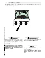
Page 29: ...OM CLOSING Pag 29 29 Manual code 119R7179GB 119R7179GB ver 3 0 3 0 07 2009 The data and information in this manual are subject to change at any time 3 5 ADJUSTING FUNCTIONS To adjust the trimmers use a small screw driver by turning it clockwise to increase or counter clockwise to reduce DELAY 2M This adjusts the delay time for the closing of the A motor see page 23 from 0 to 15 seconds We suggest ...

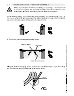
Page 30: ...ctures unauthorised personnel or children and then power up the system At this point command a gate closing action Normal speed movement Slow down Closing endstops Check endstop setting which was made when gearmotor was installed page 12 to 17 making sure whether the gate leaves reach the desired maximum opening point If necessary repeat the setting by adjusting the position of stops or cams If th...

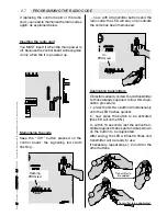
Page 31: ...replacing the control board or the radio card you need to memorise the radio codes again as explained below now with a transmitter button send the radio code the LED will stay on to indicate the code has been memorised Duplicating transmitters Clickstarisalreadycoded Toaddtransmitter to those already supplied follow this dupli cation procedure 1 press the first two button simultaneously until the L...

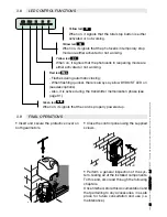
Page 32: ...t signals that the total stop button is either activated or not working Yellow led D1 When on it signals that the photocells in reopening mode are either activated or not working Yellow led D3 When on it signals that the photocells in temporary stop mode are either activated or not working Close the control panel using the supplied screws Insert and secure the protective cover on both gearmotors 3...

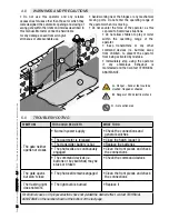
Page 33: ... on the number shown at the bottom of the last page Do not use this operator and any relative accessories for uses other than those for which they were designed the automatic opening and closing of swing gate within the limits and modes described in this manual Motostar cannot be held liable for any damage cased from wrongful erroneous or unreasonable use 5 0 TROUBLESHOOTING 4 0 WARNINGS AND PRECA...

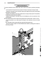
Page 34: ...nctions of all of the connected devices making sure they respond to the selections and functioning modes chosen when installed cleaning of the photocells front pieces using a water moistened rag do not use solvents or other chemical agents After disconnecting the main power supply from the general panel or sectional switch if present you may remove the gearmotor cover visually inspect the integrit...

Page 35: ...__________ ______________________ _ _ _ _ _ _ _ _ _ _ _ _ _ _ _ _ _ _ _ _ _ _ _ _ _ _ _ _ _ _ _ _ _ _ _ _ _ _______________ ______________________ _ _ _ _ _ _ _ _ _ _ _ _ _ _ _ _ _ _ _ _ _ _ _ _ _ _ _ _ _ _ _ _ _ _ _ _ _ _______________ ______________________ _ _ _ _ _ _ _ _ _ _ _ _ _ _ _ _ _ _ _ _ _ _ _ _ _ _ _ _ _ _ _ _ _ _ _ _ _ _______________ ______________________ _ _ _ _ _ _ _ _ _ _ _ _ _ _...

Page 36: ...equipment is being used DO NOT DISPOSE OF IN THE ENVIRONMENT MANUFACTURER S STATEMENT Pursuant to attachment II B of Machine Directive 98 37 CE _______________________________Themanufacturer_______________________________ CAME Cancelli Automatici S p A internet www came it e mail info came it __________________________Declaresthattheproductshereto_______________________ ___ ECLISTAR _ _ _ _ _ _ _ ...

Reviews: