Dx350_06d_oi_e.docx / Jul-20
page 56 / 67
Continutation “Parameter setting”
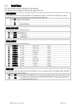
SERIAL INIT
Not valid for Modbus communication
SERIAL PROTOCOL
Not valid for Modbus communication
SERIAL TIMER (S)
Not valid for Modbus communication
SERIAL VALUE
Not valid for Modbus communication
MODBUS
This parameter enables the Modbus protocol and determines the Modbus address.
0
Do not use for Modbus protocol (Modbus disabled)
1 … 247
Modbus enabled: Serial interface is using Modbus RTU protocol
The number set here determines the Modbus node address.
Modbus Communication
The following Modbus functions are available:
Read Holding Registers and Write Multiple Registers
With the functions “Read Holding Registers” and “Write Multiple Registers” it is possible to access all
registers of the device.
All variables (actual data) and status registers are mapped to Modbus Holding Registers.
However, as all registers of the device are 32 bit registers but Modbus Holding registers are only 16 bit
registers, each register of the device requires two Holding registers.
(For this reason the use of Modbus function “Write Single Register” is not possible.)
It is only possible to access to one single register of the touchMATRIX
®
device by each read or write
operation, therefore the “Quantity (or number) of registers” in the Modbus request must always be 2.
Access to parameters
Holding Register 0x0000 / 0x0001 hex and following allow access to the device parameters.
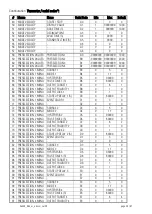
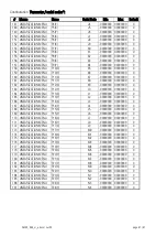
The holding register numbers for a certain parameter can be calculated by the parameter # that can be found
in the parameter table in the touchMatrix
®
device manual:
Holding Register low = (parameter #) x 2
Holding Register high = (parameter #) x 2 + 1
Example:
Access to parameter # 51 “PRESELECTION 1” by Holding Register 0x0066 and 0x0067 hex.

