Fs340_02b_oi_e.docx / Nov-21
Page 27 / 49
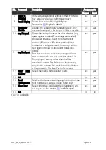
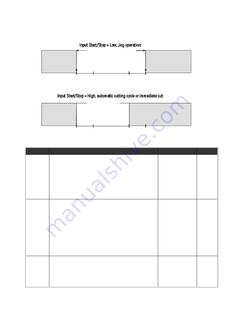
The following drawings explain the function of the software limit switches, based on the
following settings
(example): “Min.Position” =
-
20 LU, “Max.Position” = +2500 LU, “Alarm
Position” = 2000 LU:
Carriage travel range
Carriage
disabled
in backward
direction
No
function
-20
Min
Pos.
0
Zero
Pos.
+2000
Alarm
Pos.
+2500
Max
Pos.
Carriage
disabled
in forward
direction
Carriage
travel range
Unit trips to Error
state, when Min.
Pos. is touched
-20
Min
Pos.
Pos.
0
Zero
+2000
Alarm
Pos.
+2500
Max
Pos.
Output “Alarm” ist HIGH
while carriage is beyond
Alarm Pos., no Error trip
F02
Range
Default
F02.022
Set Length Counter:
Set value for material length counter at start of
automatic length operation, scaled in master encoder
pulses. When command “Start” is set the material
length counter is set to this value. Afterwards, the
register “Set length Counter” is cleared to zero (set
value only used one time).
0 … 999999
0
F02.023
Rel. Return Speed:
Sets the ratio between the actual line speed and the
maximum return speed.
For example, setting 2.00 says that, if necessary, the
return speed is permitted to be the double of the
actual line speed. The controller will however use this
maximum return speed only if really required from the
cutting process.
Only active when register “Abs Return Speed” is set to 0!
0.01 … 9.999
1.00
F02.024
Abs. Return Speed:
Sets the return speed to an absolute value scaled in
length units per minute independent of the line speed.
When set to 0, the register “Rel. Return Speed” (relative
return speed according to actual line speed) is valid!
0 … 9999999
0


