Pb340_01d_oi_e.doc / Apr-16
Page 7 / 15
3.1.
PROFIBUS connector pin assignment:
Pin:
Signal:
Function:
1
Screen
Screen / Earth connection
2
n. c.
–
3
RxD/TxD-P
Data +
4
CNTR-P (RTS)
Request To Send
5
DGND
Reference Potential (Ground)
6
VP
Power 5 V / 50 mA
7
n. c.
–
8
RxD/TxD-N
Data -
9
n. c.
–
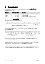
The following cables are recommended for PROFIBUS (EN 50 170 “Type-A cable“):
Impedance:
135 … 165
Capacitance:
< 30 pF / m
Loop resistance:
< 110
/ km
Wire diameter:
> 0,64 mm (0.025’’)
Conductor cross section:
> 0,34 mm²
Depending on the Baud rate, the following maximum cable length must not be exceeded:
Baud rate (kbit / s)
9,6 19,2 93,75 187,5 500
1500 3000 6000 12000
Max. cable length (m)
1200
1000
400
200
100
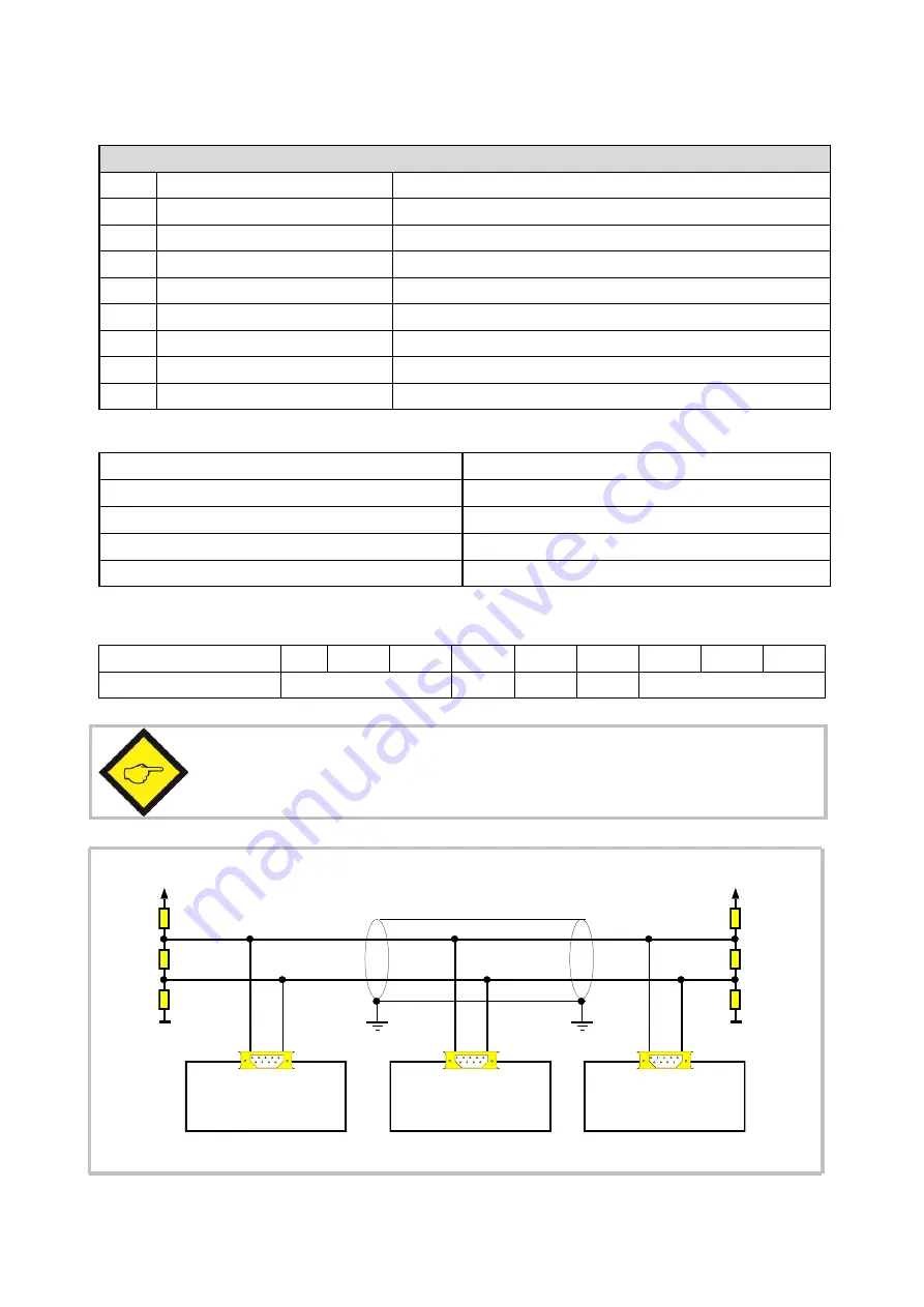
The PROFIBUS line must be terminated by a resistor network on the extreme
ends of the cable (i.e. on the first unit and on the last unit).
The shield of the cable must be connected to protection earth.
220R
Last unit
screen
390R
390R
DGND
VP (+ 5 V)
First unit
220R
390R
390R
DGND
VP (+ 5 V)
RxD/TxD-P
RxD/TxD-N
Unit


