Pb340_01d_oi_e.doc / Apr-16
Page 9 / 15
5.
Communication
During start-up of the communication the master must transmit the configuration data
according to the unit type:
Unit Type:
Configuration Data:
Meaning:
PB340
A3
hex
4 byte output data
PB306
93
hex
4 byte input data
PB541
B3
hex
4 byte input data + 4 byte output data
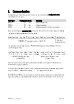
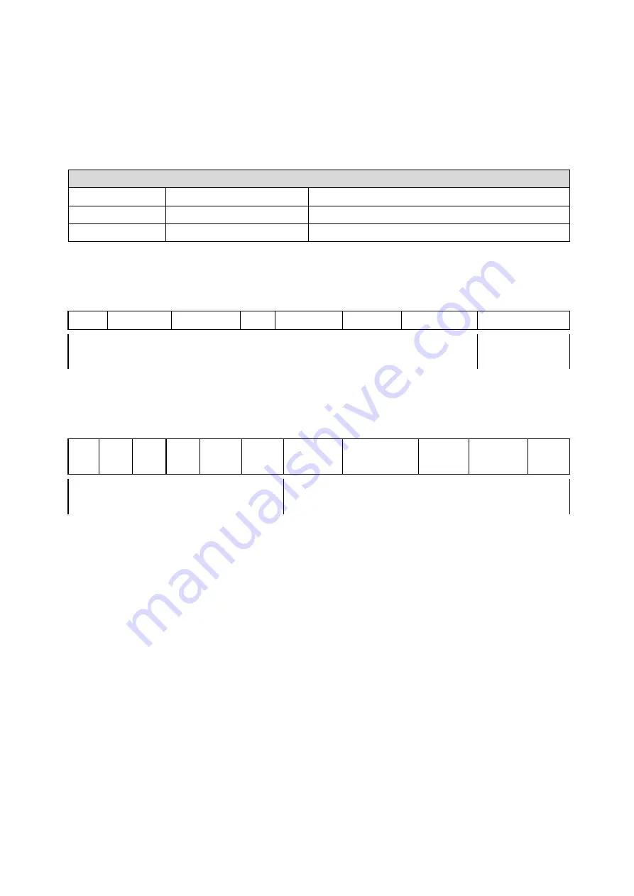
When transmitting the parameter data to the unit, the position of the decimal point in display
can be set by the user parameter “decimal point”:
status wd_fact_1 wd_fact_2 tsdr Ident high Ident low group_Ident “decimal point”
PROFIBUS-DP parameter data (
EN 50 170)
1 byte user
parameter data
The diagnosis data provide 6 bytes of PROFIBUS-DP diagnosis data and 5 byte of device
specific diagnosis data
diag
1
diag
2
diag
3
diag
4
Ident
high
Ident
low
sign_len
= 05 hex
status_type
= 81 hex
slot_nr=
00
specifier
= 00
error
= XX
PROFIBUS-DP diagnosis data
(
EN 50 170)
device specific diagnosis data
(“State PDU”)
After successful start-up the data communication begins. Both input and output data are
transmitted as signed 32-bit data.
Received output data (PB340, PB541) will be displayed immediately. When the display value
range of -99999 … 999999 is exceeded, “------” will appear in the display.
With PB306 and PB541 units the data of the thumbwheel switch set will be transferred to the
input data buffer upon pressing the ENTER button, and then transmitted with the next cycle.


