


SV21001a_e.doc / Jul-10
Page 7 / 11
2.2.
Connection of the Sine-Cosine Encoder (X5)
The encoder can be connected via the front Sub-D-9 connector marked X5 (male connector on
unit side, female connector on the encoder cable). Only encoders with differential sine-cosine
signals of 1 Vpp can be used (0.8 Vpp - 1.2 Vpp). At any time the signals sin+/sin- and cos+/cos-
must be available. Where an additional reference marker pulse is used, also the signals
ref+/ref- must be applied.
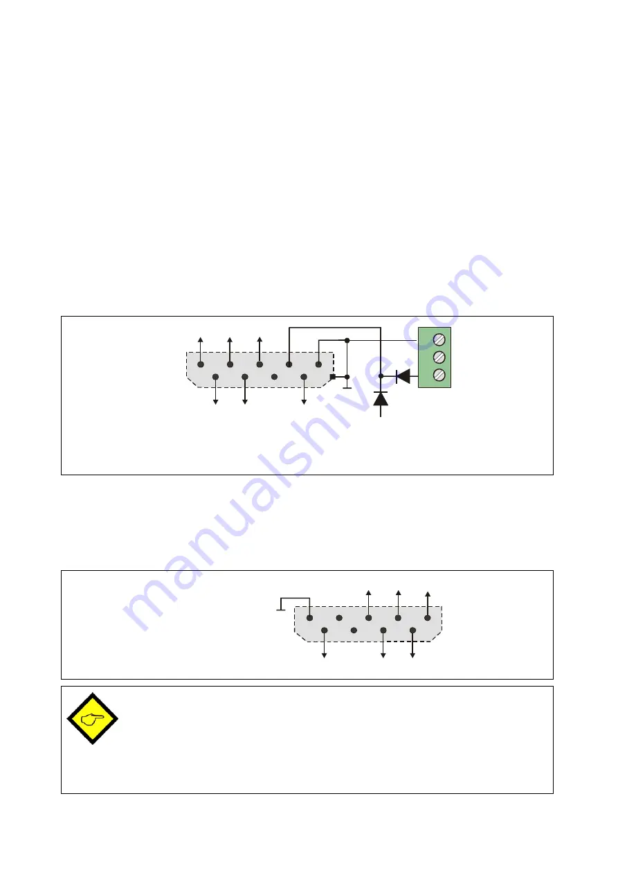
Pins 4 (+) and 5(-) of the Sub-D-connector provide an auxiliary power output for the encoder
supply. When terminal 3 of the front X6 connector is unconnected, the aux. output voltage is
automatically about 5.2 volts (max. 150 mA). Where the encoder requires another supply
voltage (e.g. 24 volts), an appropriate voltage can be applied remotely to terminal X6/3.
Please note that the metallic housing of the Sub-D input connector is internally connected to
the common GND potential of the unit.
cos+
sin-
sin+
GND
ref-
ref+
cos-
1
2
3
4
5
9
8
6
7
(nc)
1
2
3
X6
GND
+24 V
V
encoder
+5,2 V (Vcc int.)
X5
*)
*)
Sub-D-9 male
*) All differential lines (sin+/sin-, cos+/cos-, ref+/ref-) are internally terminated
by 120 ohms load resistors
2.3.
The Sine-Cosine Outputs (X1 und X3)
These two Sub-D-outputs provide an image of the sine-cosine input signals, however with a
fixed offset voltage of 2.5 volts with respect to GND. This allows a clean and trouble-free
distribution of the input signal to two target units.
cos+
sin-
sin+
GND
ref-
ref+
cos-
1
2
3
4
5
9
8
6
7
(nc)
(nc)
X1 / X3
Sub-D-9 female
•
It is mandatory to use cables with pairwise twisted wires for all sinusoidal signals
sin+/sin-, cos+/cos- and ref+/ref-.
•
For trouble-free signal transmission the target unit must provide terminating resistors
at the end of the signal line (in each case 120 ohms between and signal-)
•
Since on the inputs the unit already uses in-built termination resistors, no further
measures must be taken on the encoder side.


