7
2
3
4
5
1
6
REPLACING AN EXTERNAL CYLINDER
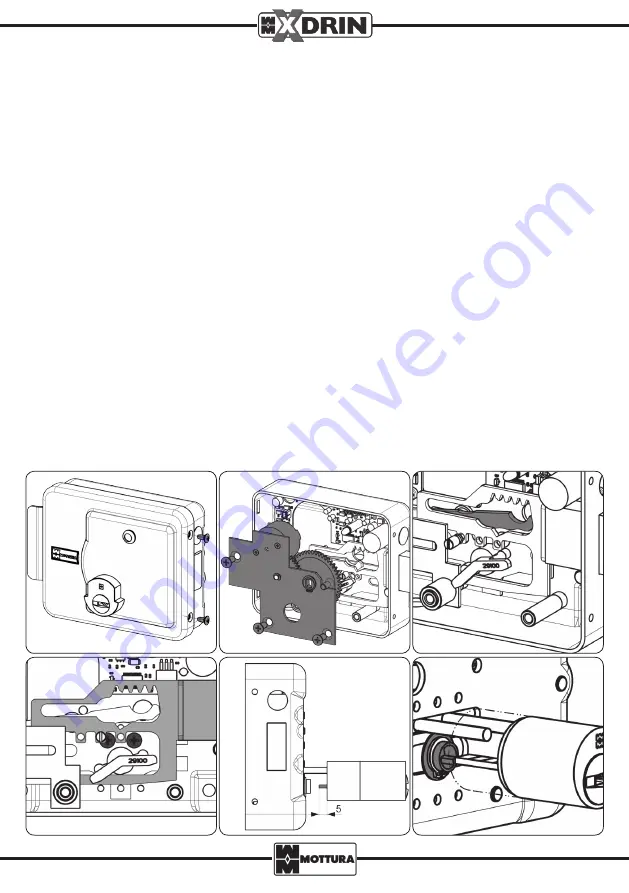
To replace the cylinder, use the supplied screws.
- Unscrew the side screws and remove the cover (Fig. 1).
- Remove the entire gear assembly (plate, 2 toothed wheels, motor) kept in place by 3 screws (Fig. 2) and disconnect
the motor connector.
- Lift the highlighted lever (Fig. 3) and move the bolt to create the space necessary for unscrewing the screws that keep
the cylinder in place (Fig. 4).
- Remove the existing cylinder.
- On the new cylinder, shorten the stem if necessary (5 mm projection from the cylinder brass spacer - Fig. 5).
- Remount the cylinder (Fig. 6).
- Reconnect the motor connector, reinsert the gear assembly, making sure that the toothed wheels are aligned correctly
with the deadbolt teeth and verifying they fit by moving the assembly manually.
- Replace the cover.
This lock offers the possibility of replacing the internal and/or external cylinder with cylinders of the same type (e.g., of
the same master system). If the gate thickness is greater than the cylinder length, you can use the special extension KIT
(optional) code 98C47ES001.
CHANGING THE KEY ENTRY
- Unscrew the side screws and remove the cover (Fig. 1).
- Remove the entire gear assembly (plate, 2 toothed wheels, motor) kept in place by 3 screws (Fig. 2) and disconnect
the motor connector.
- Lift the highlighted lever (Fig. 3) and move the bolt to create the space necessary for unscrewing the screws that keep
the cylinder in place (Fig. 4).
- Loosen the screws that keep the cylinder in place, remove the 2 screws set on the box (Fig. 7) and move the plate to the
desired key entry position – 50, 60 or 70 (Fig. 8), replace the 2 box screws and tighten the 2 cylinder screws.
- Insert the pin into the deadbolt (as shown in Fig. 9) according to the selected key entry position.
- Reconnect the motor connector, reinsert the gear assembly, making sure that the toothed wheels are aligned correctly
with the deadbolt teeth and verifying they fit by moving the assembly manually.
- Replace the cover.


