10
99348ENG - XMODE / XMODE1 - MANUALE INSTALLATORE - REV. 01
5 - CONNECTING THE POWER SUPPLY
The X-MODE and X-MODE1 locks offer a number of options based on the type of power supply and electronic board chosen for the system.
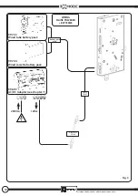
POWER SUPPLY SYSTEM (with dedicated optional accessories):
- Non-rechargeable alkaline batteries
- Network
- Non-rechargeable alkaline bat network
- Rechargeable bat network
Before switching on the power supply and/or inserting the batteries into their compartment, complete all connections and make sure they com-
ply with the wiring diagrams.
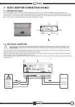
The network adapter (Art. 99.683) must be placed as close as possible to the door: It is always better to keep the 230 VAC main power supply cables
longer and the lock 12 VDC power supply cables shorter, in order to minimise voltage drop along the cable.
In case you must use longer lock power supply cables, never exceed 15 meters with a section of at least 1.5 mm2 (AWG15).
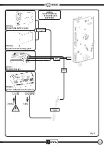
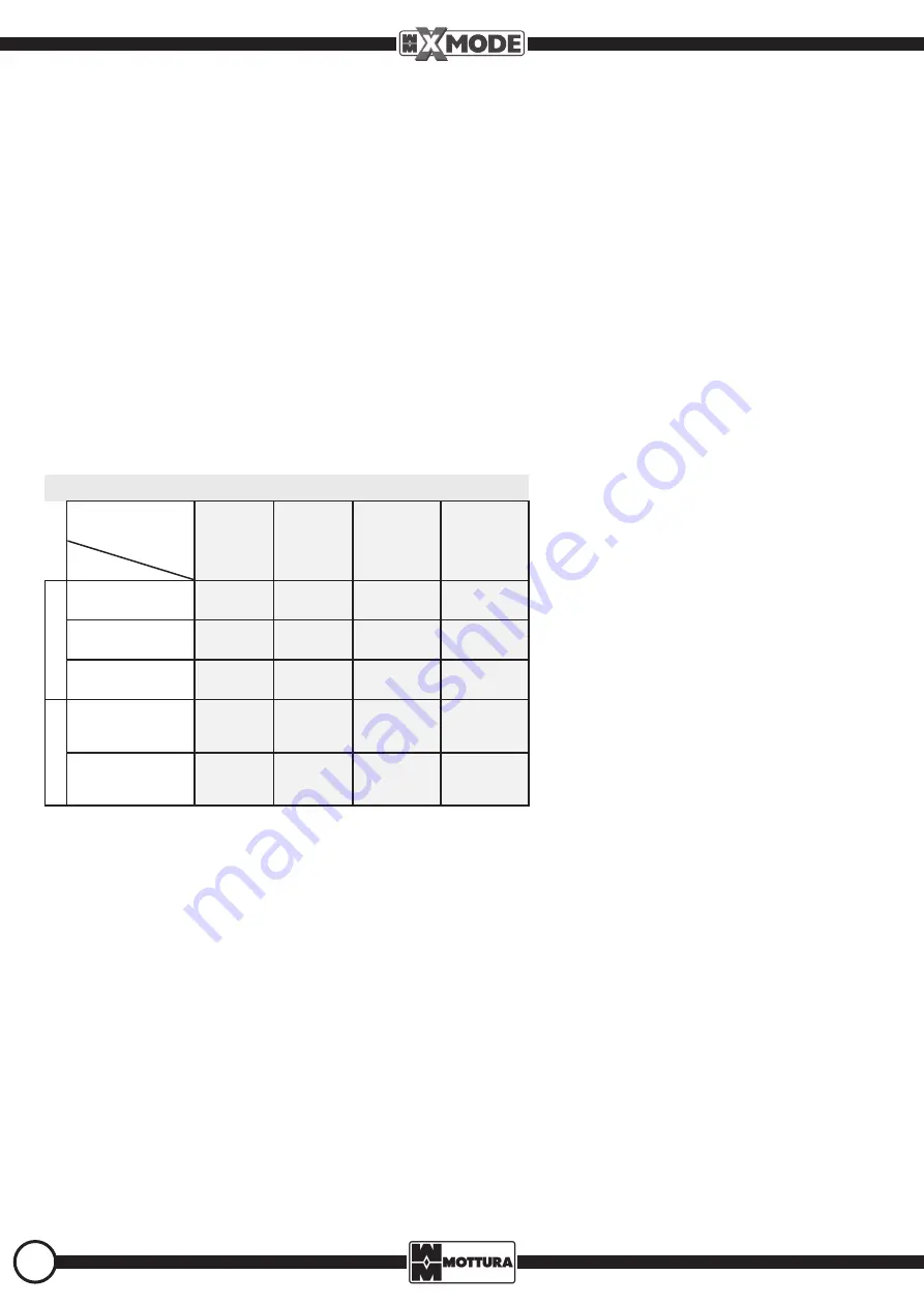
The following table lists the possible power supply combinations, specifies the wiring diagram to be followed for each, and provides the codes for
the used cables and components.
XMODE M2.0 WIRINGS
POWER
SUPPLY
ALKALINE
BATTERIES
MAINS
ALKALINE
BATTERIES
+
MAINS
RECHARGEABLE
BATTERIES
+
MAINS
WIRING
BATTERY PACK
Fig. A
Fig. C
Fig. D
MAINS
Fig. B
Fig. C
Fig. D
BATTERY CHARGER
Fig. D
COMPONENT
BATTERY CHARGER
Fig. D
AC/DC ADAPTER
Fig. B
Fig. C
Fig. D
NOTE :
If you use the battery charger (art. 99 711), please note that the cables have been designed to be mounted inside the door. Refer to the
installation instructions provided with the article.


