18
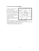
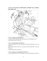
out of the engaged HANDLE PIVOT JOINT CAP-T (141) and HANDLE PIVOT JOINT CAP-B
(142).
2) Remove the HANDLE PIVOT JOINT CAP-T (141) and HANDLE PIVOT JOINT CAP-B (142)
from HANDLE CRANK FRAME (94) by opening these two parts while pushing the edge of the
engaged HANDLE PIVOT JOINT CAP-T (141) and HANDLE PIVOT JOINT CAP-B (142).
3) Reassemble the parts in reverse order.
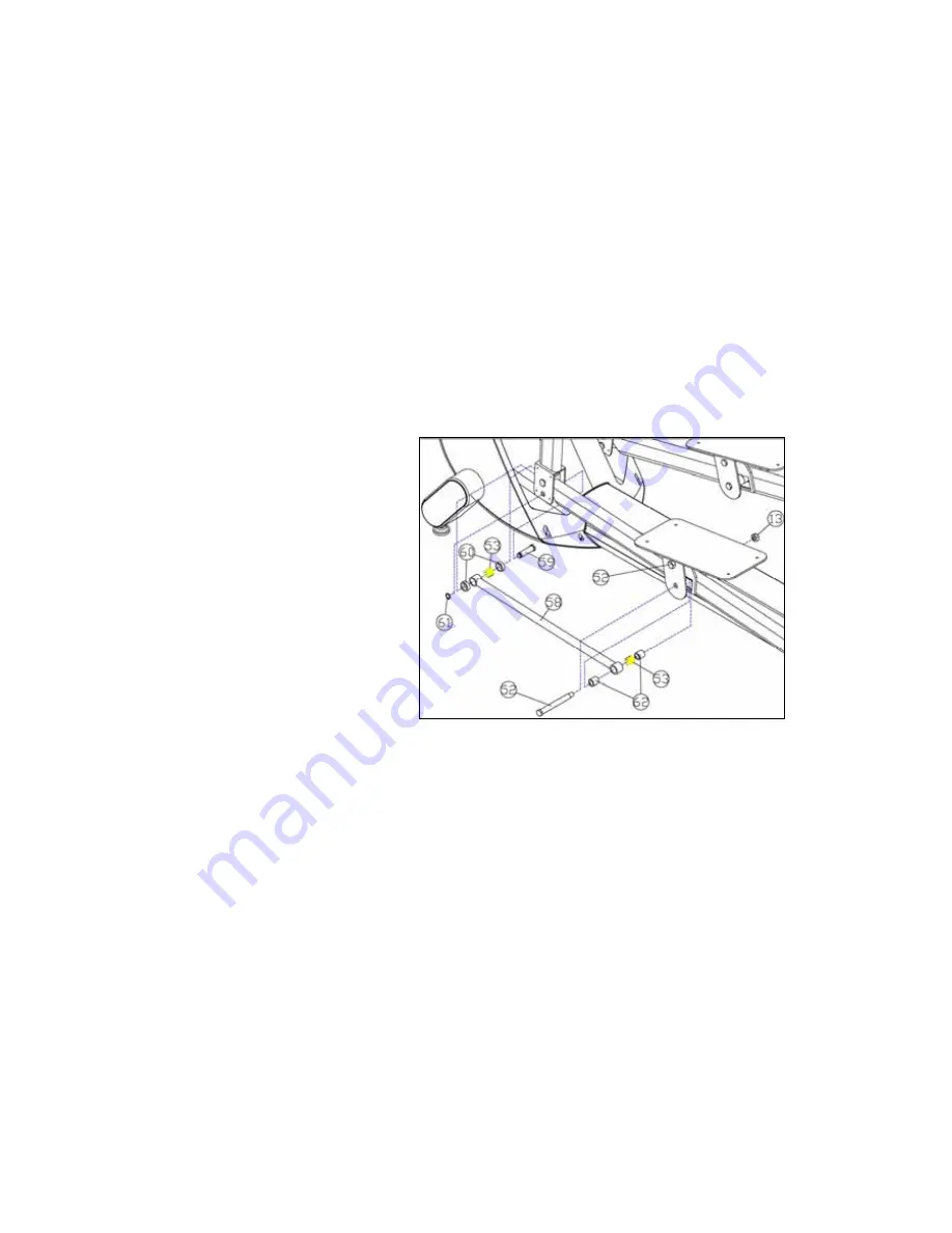
2.8 How to Replace the NEEDLE BEARINGS inside the PEDAL COUPLER
(Or How to Replace the OILLESS BUSH inside the PEDAL COUPLER with
NEEDLE BEARINGS)
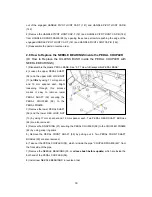
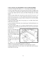
1) Disassemble the plastic PEDAL BASE. See “2.7.1 How to Disassemble PEDAL BASE”
2) Loosen the upper PEDAL SHAFT
(52) and the upper HEX LOCK NUT
(13)
a little
by using 17 mm spanner
and 19 mm spanner each. Slight
loosening through this process
makes it easy to remove lower
PEDAL SHAFT (52) securing the
PEDAL COUPLER (58) to the
PEDAL FRAME.
3) Remove the lower PEDAL SHAFT
(52) and the lower HEX LOCK NUT
(13) by using 17 mm spanner and 19 mm spanner each. Two PEDAL REAR SHAFT BUSHes
(62) are also removed.
4) Remove the SNAP RING (61) securing the PEDAL COUPLER (58) to the COUPLER FRAME
(42) by using snap ring pliers.
5) Remove the PEDAL FRONT SHAFT (59) by pulling out it. Two PEDAL FRONT SHAFT
BUSHes (60) are also removed.
6) Take out the PEDAL COUPLER (58), which is inside the pipe “COUPLER FRAME (42)”, from
the front side of the pipe.
7) Remove the NEEDLE BEARINGS (53, or
oil-less bush before update
) which are inside the
both end of the PEDAL COUPLER (58).
8) Install new NEEDLE BEARINGS in reverse order.
Summary of Contents for M770E
Page 24: ...23 3 1 How to Replace the LCD Screen in Model M770EL Fig 3a CONSOLE POST ...
Page 25: ...24 Fig 3b CONSOLE ...
Page 33: ...32 7 Install new AUDIO INTERFACE DOWNLOAD Board 24 in reverse order ...
Page 40: ...39 4 1 Cable Connection Block Diagram 1 MPU PCB on M770EL MPU_FRONT Display MPU_BACK MAIN ...
Page 41: ...40 2 MPU PCB on M770E ...
Page 42: ...41 3 A D BOARD on M770EL ...
Page 43: ...42 4 POWER BOARD 4 1 M770EL DRIVE Board SMPS 5V LCD POWER ADAPTER 4 2 M770E DRIVE Board ...
Page 60: ...59 RCA 6A YELLOW Video Input ...
Page 69: ...68 ...


