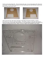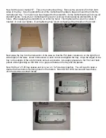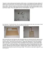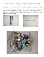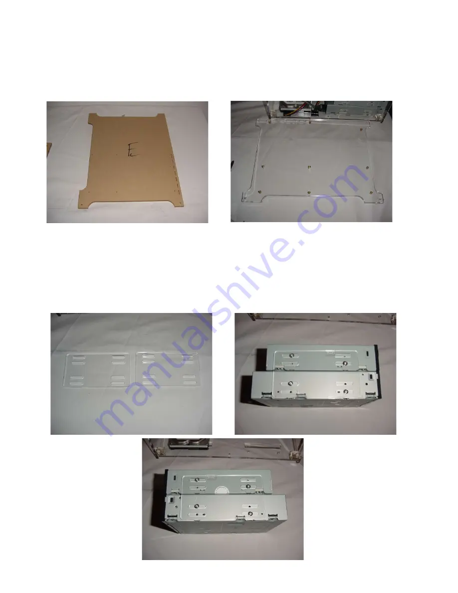
Now find the panel marked “E”. This is the motherboard tray. Remove the protective film from both
sides of the tray. Take the standoffs out of the motherboard hardware bag and mount them into the
motherboard tray. Ten holes have been tapped for the standoffs. Some motherboards will not use all
standoff points. Consult your motherboard manual or examine it before placing all standoffs in the
holes. When applying the standoffs do so at first by hand. Then tighten with a wrench or pliers if
needed. Do not over tighten. Over tightening may result in stripping of the threads on the acrylic.
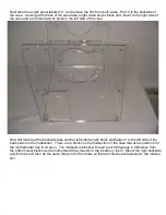
Next place the tray into the midsection of the case so that the PCI plate cutouts are on the right (front
side angle) of the case. Insert 3mm screws in each corner and tighten the tray. Align the edges of the
tray to the outside of the acrylic blocks as best as possible. Also apply pressure to the front and back
panels while tightening so that little or no gaps are between the tray and the panels.
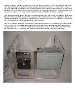
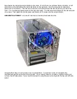
Now find the 2 x 5.25 bay spaces and join your 2 x 5.25 devices together. You will need to keep a
device that has bottom mounting holes on the bottom. Most CDR or DVD devices will have these.
Join the devices as shown below.


