BFA-Series & NFA-Series Operation Instructions
Key Features
- Various models that range from 0.9 - 39 lbf.in
- Robotic style electric screwdriver for automated and fixtured applications.
- Drivers include a front mounting flange.
- High performance brushless motor design provides durability and reduces the standard maintenance costs for electric
screwdrivers.
- Designed for high production environments. Minimal heat build-up even when tool is operated continuously.
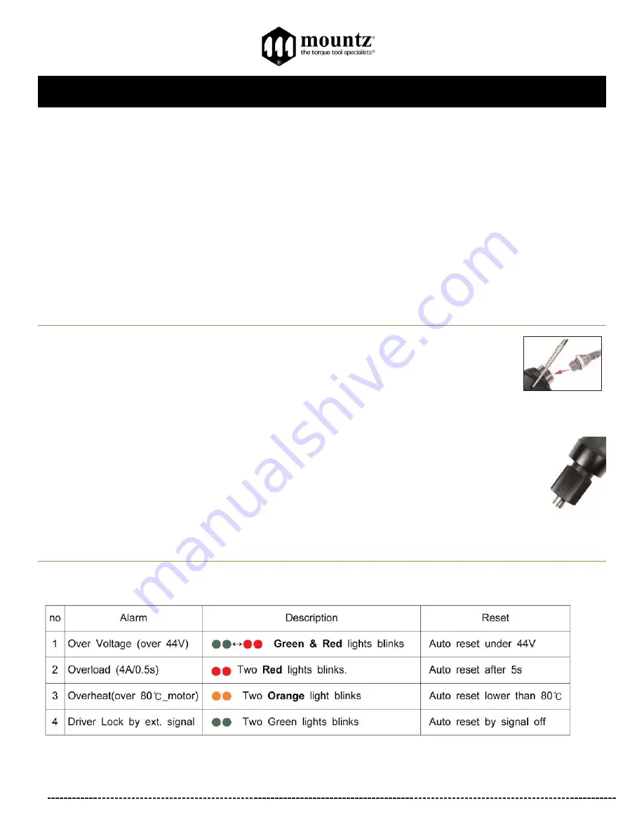
- Over Heat Protection (OHP) and Over Current Protection (OCP) protect driver from damage or malfunction. Features a LED
display that signals the tool status for the operator to view.
- Can be connected with the Scout Screw Counter.
- Requires STC40-FA transformer (power supply).
- All models are ESD designed and prevent the occurrence of electrostatic discharge, which improves production yields,
manufacturing costs, product quality, product reliability, reputation and profitability.
- Ensures accuracy in fastening with precision automatic shut-off clutch once preset torque is achieved.
- External torque adjustment scale.
- Forward and reverse direction by switch. Start and stop output signals.
Corporate Headquarters:
1080 North 11th Street, San Jose, CA 95112 Phone: (408) 292-2214 Fax: (408) 292-2733
www.mountztorque.com
Page 2
General Operation for BFA-Series and NFA-Series models
1. Attach power tool cable to the BFA or NFA screwdriver and the transformer. Make sure notch in plug lines up
with the notch on the socket. Tighten knurled ground ring.
2. Plug in power cord to the back of the transformer and power outlet. Flip power switch to “ON” position located
on the back of transformer.
3. Select a bit. Retract the bit collar. Insert the bit and release the retracted collar. To avoid damaging
fasteners, make sure the proper bit is suitable for the head of the fastener.
4. The torque limit is determined by the tension of the coil spring housed in the torque adjustment nut. The tighter the coil spring is
wound the higher the torque limit is raised. See charts on pages 9-10 to determine the appropriate torque
adjustment setting.
5. Rotate the torque adjustment nut to set the torque limit. Turn clockwise to increase torque and counter clockwise to
decrease torque. The scale adjacent to the Torque Adjustment Nut is a reference guide. The torque output from the
driver can change depending on various fastening factors like friction, type of joint, and the type material being used
like a washer.
6. Turn driver on and check for proper rotation. FOR-clockwise, REV-counterclockwise.
torque
adjustment nut
Alarm display on the screwdriver by LED


