background image

5/16

NT 1401-G00 10 18 TYPHON II  e

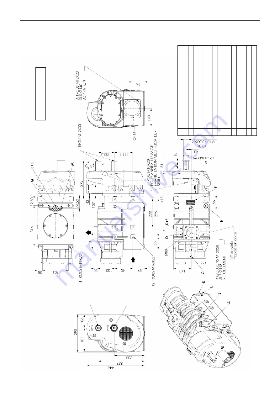
1. OVERALL DIMENSIONS (continued)

13R/15L - 19R/22L

13R 

19R

15L 

22L

Poids / W

eight : 173 kg

A

Jauge d’huile / Oil gauge

B

Filtre à huile / Oil filter

C

V

idange / Draining cap

D

Contrôle pression refoulement G1/4”

Outlet pressure control G1/4”

E

Contrôle 

T° refoulement G1/4”

Outlet 

T° control G1/4”

F

Plaque signalétique / Identification plate

G

Prise pression huile / Oil pressure plug

H

Bouchon 3/4 (pour montage jauge d’huile à droite)

3/4 cap (for right oil gauge installation)

J

Prise vitesse G1/4” / Speed control G1/4”

K

Contrôle pression aspiration G1/4”

Inlet pressure control G1/4”

L

Contrôle 

T° aspiration G1/4” / Inlet 

T° control G1/4”

M

Bouchon magnétique G3/8” / Magnetic plug G3/8”

Summary of Contents for 15L

Page 1: ... the equipment Your distributor Z I La Plaine des Isles F 89000 AUXERRE FRANCE Tel 33 0 3 86 49 86 30 Fax 33 0 3 86 49 87 17 contact mouvex com www mouvex com WARRANTY TYPHON II screw compressors are covered 24 months by warranty within the limits mentioned in our General Sales Conditions The use of the BSC3 oil carries our warranty from 24 to 36 months In case of a use other than that mentioned i...

Page 2: ...COMPRESSOR 14 4 1 Lubricant recommendations 14 4 2 Filling of lubricant 14 4 3 Operation 15 4 4 Starting up 15 5 MAINTENANCE 16 5 1 Maintenance schedules 16 5 2 Compressor oil change procedure 16 5 3 Troubleshooting 16 TABLE OF CONTENTS Page ADDITIONAL DOCUMENTATION The table below gives the list of instructions in addition to this central instruction TYPHON II application Instructions Spare parts...

Page 3: ...E COM PRESSED AIR NOT TO PUMP GASES LIQUIDS POWDERS OR CONDENSATES THOUGH THE COMPRESSOR TO DO SO WOULD VOID THE WARRANTY LIFTING POINTS The compressor can be picked up from underneath to be transported Discharge flanges threads can be used to install a lifting lug in order to transport the compressor WARNING IT IS IMPERATIVE TO APPLY THE TRUCK PARKING BRAKE AND TO BLOCK THE WHEELS BEFORE ANY INTE...

Page 4: ...nt G1 4 Outlet T control G1 4 F Plaque signalétique Identification plate G Prise pression huile Oil pressure plug H Bouchon 3 4 pour montage jauge d huile à droite 3 4 cap for right oil gauge installation J Prise vitesse G1 4 Speed control G1 4 K Contrôle pression aspiration G1 4 Inlet pressure control G1 4 L Contrôle T aspiration G1 4 Inlet T control G1 4 M Bouchon magnétique G3 8 Magnetic plug G...

Page 5: ...ssure control G1 4 E Contrôle T refoulement G1 4 Outlet T control G1 4 F Plaque signalétique Identification plate G Prise pression huile Oil pressure plug H Bouchon 3 4 pour montage jauge d huile à droite 3 4 cap for right oil gauge installation J Prise vitesse G1 4 Speed control G1 4 K Contrôle pression aspiration G1 4 Inlet pressure control G1 4 L Contrôle T aspiration G1 4 Inlet T control G1 4 ...

Page 6: ...control G1 4 E Contrôle T refoulement G1 4 Outlet T control G1 4 F Plaque signalétique Identification plate G Prise pression huile Oil pressure plug H Bouchon 3 4 pour montage jauge d huile à droite 3 4 cap for right oil gauge installation J Prise vitesse G1 4 Speed control G1 4 K Contrôle pression aspiration G1 4 Inlet pressure control G1 4 L Contrôle T aspiration G1 4 Inlet T control G1 4 M Bouc...

Page 7: ...e compression stage by means of labyrinth seals These seals do not enter in contact with the shaft and are not subject to wear Thanks to their technology TYPHON II compressors are reliable and have a long service life TYPHON II compressors need very limited maintenance which reduce vehicle downtime TYPHON II version 20R 13R 15L and 19R 22L drive speed were defined so as to drive it directly throug...

Page 8: ...ient temperature and air inlet temperature 20 C atmospheric pressure 1013 mbars 2 3 Operating ranges The operating ranges specified in the TECHNICAL CHA RACTERISTICS give the conditions that must be respected on mounting and packaging of the TYPHON II compres sors in order to be able to benefit from the guarantees for these pieces of equipment The use of compressors outside of their operating spee...

Page 9: ...haust to the atmosphere may be more than 200 C Make sure that the flow of hot air does not cause any damage to the surrounding elements If necessary provide for protections that prevent operators from touching the hot parts The maximum acceptable temperature at suction as a function of equipment operating conditions is given in the TECHNICAL CHARACTERISTICS 2 3 2 CONDITIONS AT DISCHARGE The TYPHON...

Page 10: ... can lead to mechanical ruptures that may create major property damage and or serious injuries 2 3 4 ACCEPTABLE OIL PRESSURE RANGE The oil pressure is measured at the tap point located on the synchromesh gear box item G on the outline drawings In operation the surface temperature of a compressor and parts close to him may reach high temperatures liable to cause significant burns and inflammation o...

Page 11: ...11 16 NT 1401 G00 10 18 TYPHON II e 3 MULTIPLIER 13R 15L 19R 22L Front view of compressor 3 1 Cross section ...

Page 12: ...al 59 The shaft will be held in place as the compressor slopes If necessa ry use 2 screws M10 to extract the lid Remove from a block the shaft 27 ring 53 circlips 63 gear 7 a complete roller bearing 68 the inner ring of the second roller bearing 68 If necessary use the tappings M8 found top right and bottom left of the lid to extract the lid Scrape the Loctite 510 remaining on the joint sur face o...

Page 13: ...the screws 835 and rings BS 834 keeping the lid in place 3 Screw at torque 24 Nm 10 Unscrew the screw holding the fan in place 819 Inject a drop of Loctite 243 Replace the screw Mount the fan 819 and screw up the relevant screw to screw it to the shaft 809 NB the fan wings can cut use suitable protection Wipe off the excess Loctite On the cover 820 check the presence of spacers 826 in the sleeves ...

Page 14: ...to tolerate 35 C That implies the following constraints Oil must be replaced every 100 operating hours Imperative return to the BSC3 when the temperature becomes again positive Oils BSC and SAE are miscible the passage of the one with the other thus does not imply particular procedure of cleaning Compressors can be used with an external oil cooler in case of intensive applications see Instructions...

Page 15: ...d nearby are thus susceptible of provoking serious burns and property damage Be careful to not approach elements that are sensitive to heat and affix plates informing users that the compressor is hot to prevent any risk of burns 4 4 Starting up BEFORE starting compressor open all air valves neces sary to vent the tank and compressor to atmosphere Verify there is no possibility of operating at pres...

Page 16: ... splits and tears Replace or repair as necessary Inspect compressor system piping and components Clean or repair as necessary Monthly Check oil level add the necessary volume if necessary Check for cleanliness the breather inside the oil jauge clean with an air blower if necessary 5 2 Compressor oil change procedure Oil gauge See LUBRICANT RECOMMENDATIONS Unscrew and remove the oil filter with its...

Reviews: