5
4
Quick Start Guide
|
SCREW COMPRESSORS – MH6
CONTROL CHECK LIST
Installation Of The Compressor PTO & MH6 Compressor Set
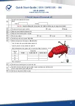
C. Compressor’s Suction
1
Filter :
o
1
Pre-cleaner in place.
o
2
Clogging indicator visible.
o
3
Cartridge in place and clean.
2
Hose :
o
4
Clean inside.
o
5
Not folded, fastened in order to avoid any banging.
o
6
Heat shrinkable sleeve in place at both ends.
o
7
Collars in place and tightened.
D. Compressor’s Discharge
o
1
The graphite flange gasket is in place.
o
2
Flange screws tightened at 44 Nm.
o
3
A 45° or 90° elbow is fitted on the flange (a vertical pipe between the flange and the elbow is allowed).
o
4
The discharge hose delivered is fitted on that elbow.
o
5
Threaded connexions are waterproof.
o
6
There is a plug at the end of the pipe.
o
7
Relief valve turned in the right direction.
o
8
The waterproofness of the whole piping has to be checked.
o
9
Relief valve orientation.
EN


