
MTUX/IA-63-00 – Installation Manual
101
Date: 2017/02/17
00
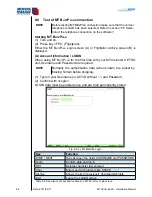
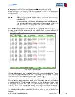
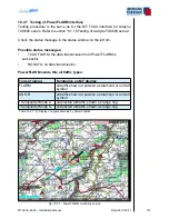
10.2.7 Testing of PowerFLARM interface
Testing procedure is the same as for the MT TCAS Interface for Avidyne
TAS600 series. Refer to section “8.1.10 Testing of Avidyne TAS600 series”.
Check the status message in the status window on the left rim.
Possible status messages:
TCAS FLARM: the data transmission from PowerFLARM is
successful.
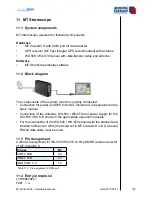
NO DATA: no data transmission.
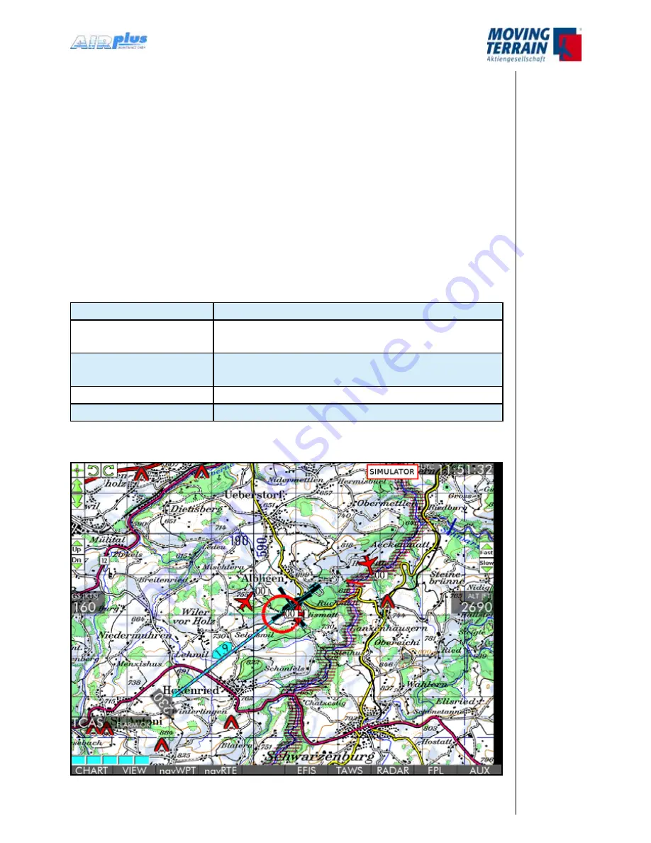
PowerFLARM sends this airtraffic types:
Type of signal
Symbolics on MT display
FLARM
airtraffic shown at position as diamond or aircraft
symbol
ADS-B
airtraffic shown at position as diamond or aircraft
symbol
Transponder Mode C
undirected airtraffic, shown as range ring
Transponder Mode S
undirected airtraffic, shown as range ring
Table 10.2.7 (1): Display of signals detected by PowerFLARM
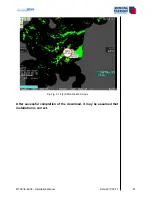
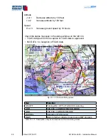
Fig. 10.2.7: PowerFLARM monitoring screen
•
•
Summary of Contents for MT-VisionAir X ETSO
Page 10: ...MTUX IA 63 00 Installation Manual 10 Date 2017 02 17 INTENTIONALLY LEFT BLANK ...
Page 12: ...MTUX IA 63 00 Installation Manual 12 Date 2017 02 17 INTENTIONALLY LEFT BLANK ...
Page 28: ...MTUX IA 63 00 Installation Manual 28 Date 2017 02 17 INTENTIONALLY LEFT BLANK ...
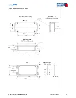
Page 107: ...MTUX IA 63 00 Installation Manual 107 Date 2017 02 1700 12 4 Dimensions in mm ...
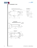
Page 112: ...MTUX IA 63 00 Installation Manual 112 Date 2017 02 17 13 3 Dimensions in mm ...
Page 125: ...MTUX IA 63 00 Installation Manual 125 Date 2017 02 1700 INTENTIONALLY LEFT BLANK ...
Page 137: ...MTUX IA 63 00 Installation Manual 137 Date 2017 02 1700 ...
Page 138: ...MTUX IA 63 00 Installation Manual 138 Date 2017 02 17 ...
Page 139: ...MTUX IA 63 00 Installation Manual 139 Date 2017 02 1700 INTENTIONALLY LEFT BLANK ...
Page 146: ...MTUX IA 63 00 Installation Manual 146 Date 2017 02 17 INTENTIONALLY LEFT BLANK ...