MTUX/IA-63-00 – Installation Manual
120
Date: 2017/02/17
16. MT Mission Management System (MT-MMS)
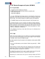
16.1 Requirements
1. A supported Iridium Satphone or Modem
The MMS software module has been tested successfully with:
Iridium 9555 Satphone
Iridium 9575 Satphone
2. An active SBD (Short Burst Data) contract on the Satphone, linked to the
appropriate e-mail addresse(s) which will be used for tracking (see chapter MT
OPS Center). The contract is linked to the IMEI number of the telephone.
3. The MMS module must have been purchased for this VisionAir X unit.
4. The MT-VisionAir X must be connected via USB to the Iridium Satphone
NOTE: if the central connector is used, then it is necessary to install an external
USB hub between unit and satphone (this applies for MT-VisionAir X with SP
boards, TT board units can be used directly. To check board type use: <AUX>
<SETUP> <VERSION> <VERSION>).
5. The Satphone must have a clear view of the sky or be connected to an
external antenna.
16.2 Usage
NOTE: The Iridium Satphone must be switched on manually during preflight
and should be turned off manually, as well, after the flight. The MT-VisionAir
X software cannot control the Satphone power.
No other operation should be needed on the Satphone while using the MMS
functions.
To turn on aircraft tracking: on the VisionAir X button bar press AUX --> MMS
--> TrkON
When tracking is on there will be a thin gray message area on the bottom left
of the map screen (just to the right of the brightness indicator). It will show the
MMS tracking status, including error conditions.
By default the system will try to send a position report every 60 seconds
approximately, but will retry every 15 seconds in case of error.
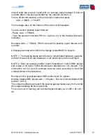
Depending on several factors the ground tracking software (MT OPS
•
•
Summary of Contents for MT-VisionAir X ETSO
Page 10: ...MTUX IA 63 00 Installation Manual 10 Date 2017 02 17 INTENTIONALLY LEFT BLANK ...
Page 12: ...MTUX IA 63 00 Installation Manual 12 Date 2017 02 17 INTENTIONALLY LEFT BLANK ...
Page 28: ...MTUX IA 63 00 Installation Manual 28 Date 2017 02 17 INTENTIONALLY LEFT BLANK ...
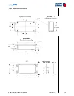
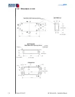
Page 107: ...MTUX IA 63 00 Installation Manual 107 Date 2017 02 1700 12 4 Dimensions in mm ...
Page 112: ...MTUX IA 63 00 Installation Manual 112 Date 2017 02 17 13 3 Dimensions in mm ...
Page 125: ...MTUX IA 63 00 Installation Manual 125 Date 2017 02 1700 INTENTIONALLY LEFT BLANK ...
Page 137: ...MTUX IA 63 00 Installation Manual 137 Date 2017 02 1700 ...
Page 138: ...MTUX IA 63 00 Installation Manual 138 Date 2017 02 17 ...
Page 139: ...MTUX IA 63 00 Installation Manual 139 Date 2017 02 1700 INTENTIONALLY LEFT BLANK ...
Page 146: ...MTUX IA 63 00 Installation Manual 146 Date 2017 02 17 INTENTIONALLY LEFT BLANK ...

