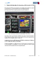

MTUX/IA-63-00 – Installation Manual
19
Date: 2017/02/17
00
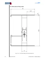
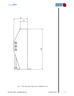
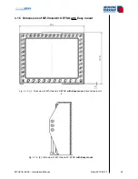
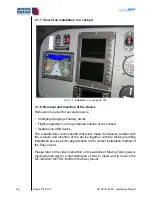
3.1.3 Panel cutout
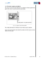
The Easy mount must be firmly attached to the cockpit panel with screws.
Please use countersunk screws or rivets for installation in the instrument
panel (or onto the angled rail) as space of 158 mm including any protruding
screwheads must remain available for the device.
Panel cutout dimensions:
Width: 157.5 mm minimum (with latches in the rack), 160.5 mm optimum
Height: 128 mm
Depth: 46 mm
(all dimensions incl. 0.5 mm tolerance)
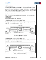
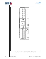
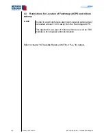
1. Installation for panel clearance of 160.5 mm
Mounting flush with cockpit panel or tilted mounting due to improved readability
angle (e.g. for mounting at co-pilots side).
Fig. 3.1.3 (1): Panel clearance 160.5 mm
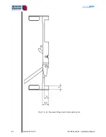
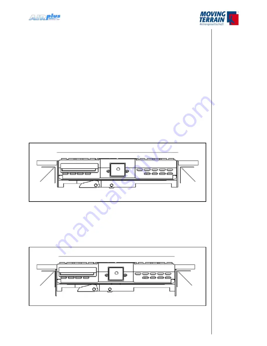
2. Installation for panel clearance of 158 mm
Mounting at the rear side of the panel: to flush the unit with the panel relocate
the screws in the side mounting brackets.
Fig. 3.1.3.(2): Panel clearance 158 mm
157.5 mm
Panel
Angle
bracket for
mounting
Panel
Angle
bracket for
mounting
160.5 mm
Panel
Angle
bracket for
mounting
Panel
Angle
bracket for
mounting
Summary of Contents for MT-VisionAir X ETSO
Page 10: ...MTUX IA 63 00 Installation Manual 10 Date 2017 02 17 INTENTIONALLY LEFT BLANK ...
Page 12: ...MTUX IA 63 00 Installation Manual 12 Date 2017 02 17 INTENTIONALLY LEFT BLANK ...
Page 28: ...MTUX IA 63 00 Installation Manual 28 Date 2017 02 17 INTENTIONALLY LEFT BLANK ...
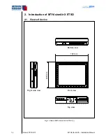
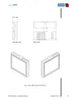
Page 107: ...MTUX IA 63 00 Installation Manual 107 Date 2017 02 1700 12 4 Dimensions in mm ...
Page 112: ...MTUX IA 63 00 Installation Manual 112 Date 2017 02 17 13 3 Dimensions in mm ...
Page 125: ...MTUX IA 63 00 Installation Manual 125 Date 2017 02 1700 INTENTIONALLY LEFT BLANK ...
Page 137: ...MTUX IA 63 00 Installation Manual 137 Date 2017 02 1700 ...
Page 138: ...MTUX IA 63 00 Installation Manual 138 Date 2017 02 17 ...
Page 139: ...MTUX IA 63 00 Installation Manual 139 Date 2017 02 1700 INTENTIONALLY LEFT BLANK ...
Page 146: ...MTUX IA 63 00 Installation Manual 146 Date 2017 02 17 INTENTIONALLY LEFT BLANK ...


