
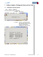

MTUX/IA-63-00 – Installation Manual
40
Date: 2017/02/17
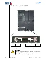
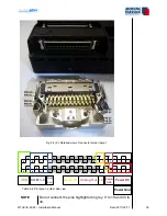
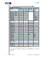
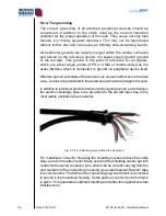
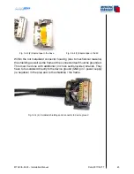
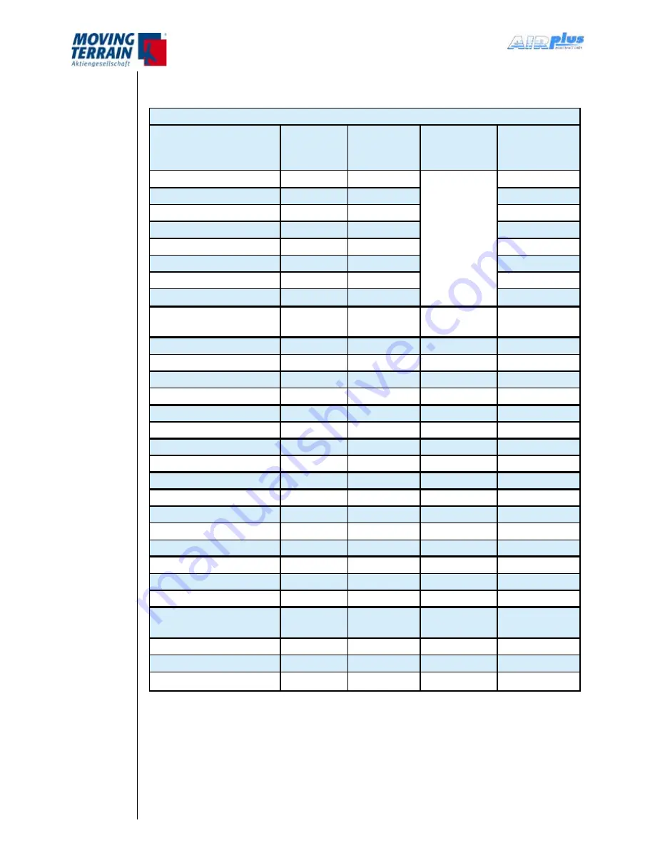
5.5 Pin layout of the central connector (50-pin MDR)
Standard Pin Assignment
Signal
Central
connector
pin
Pin at
Common
Connector
Common
Connector
Common
Wire
Color
Power DC 12–36 V
26
2
2 pin socket red
Power DC 12–36 V
27
2
red
Power DC 12–36 V
28
2
red
Power DC 12–36 V
29
2
red
PWR GND
1
1
blue/black
PWR GND
2
1
blue/black
PWR GND
3
1
blue/black
PWR GND
4
1
blue/black
DC Power out
30
3
4 pin socket red
COM 1 RxD
45
2
9 pin Sub-D *
COM 1 TxD
46
3
*
COM 2 RxD
47
2
9 pin Sub-D *
COM 2 TxD
48
3
*
COM 3 RxD
20
2
9 pin Sub-D *
COM 3 TxD
21
3
*
COM 4 RxD
22
2
9 pin Sub-D *
COM 4 TxD
23
3
*
GND COM 1–4
19
5
9 pin Sub-D *
USB +5V
24
1
red
USB data –
25
2
USB
white
USB data +
50
3
green
USB GND
49
4
black
Audio out
7
Audio in
8
Audio GND
4
DIM analog in
31
Analog out 1
5
Analog out 2
6
Analog GND
4
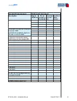
Table 5.5: Pin layout of central connector (continued on next page)
* the colors for COM test cables are not standardized - can not be
specified.
Summary of Contents for MT-VisionAir X ETSO
Page 10: ...MTUX IA 63 00 Installation Manual 10 Date 2017 02 17 INTENTIONALLY LEFT BLANK ...
Page 12: ...MTUX IA 63 00 Installation Manual 12 Date 2017 02 17 INTENTIONALLY LEFT BLANK ...
Page 28: ...MTUX IA 63 00 Installation Manual 28 Date 2017 02 17 INTENTIONALLY LEFT BLANK ...
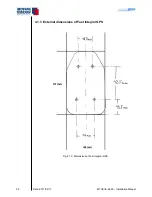
Page 107: ...MTUX IA 63 00 Installation Manual 107 Date 2017 02 1700 12 4 Dimensions in mm ...
Page 112: ...MTUX IA 63 00 Installation Manual 112 Date 2017 02 17 13 3 Dimensions in mm ...
Page 125: ...MTUX IA 63 00 Installation Manual 125 Date 2017 02 1700 INTENTIONALLY LEFT BLANK ...
Page 137: ...MTUX IA 63 00 Installation Manual 137 Date 2017 02 1700 ...
Page 138: ...MTUX IA 63 00 Installation Manual 138 Date 2017 02 17 ...
Page 139: ...MTUX IA 63 00 Installation Manual 139 Date 2017 02 1700 INTENTIONALLY LEFT BLANK ...
Page 146: ...MTUX IA 63 00 Installation Manual 146 Date 2017 02 17 INTENTIONALLY LEFT BLANK ...