MTUX/IA-63-00 – Installation Manual
42
Date: 2017/02/17
5.6 The central plug cable assembly for MT-VisionAir X ETSO
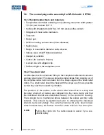
5.6.1. Recommended tools and materials
Temperature-controlled soldering iron (soldering max.2mm width (better:
1.5 mm) set to about 350 °C
Solder with integrated solder flux, 0.5 mm (no lead-free solder)
Stripper with fixed cable diameters
Tweezers
Hot air gun
Shrink on tubing various sizes (2mm diameter)
Kapton tape
Range of reasonable diameter cable sleeves
Various sizes small Phillips screwdriver
Scalpel or penknife
Cutters (for example: Knipex)
A small vice with alligator clip.
Sufficient light in the workplace, torch
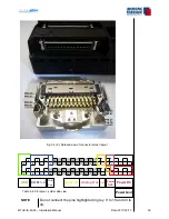
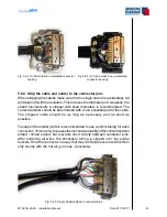
5.6.2. The strain relief
A cable sleeve with a diameter fitting to the complete cable bunch ensures
a proper strain relief. This sleeve protects single cables from slipping out of
the complete cable bunch and also from the sharp edges of the strain relief
clamp. The strain relief should be fixed with the screws as firm as possible
so that they can′t be loosend by vibration.
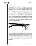
The position of the cables in the strain relief should be in a way that
the outer shells of all cables are clamped into the cable clamp and that
the individual strands are distributed loosely in the connector housing.
There should be no mechanical stress between the solder and the cable
network. This should be determined prior to stripping the individual
strands quite accurately. The external connector pins need longer
wires because they are further from the strain relief as the inner pins.
NOTE
Pulling the cable into the cable sleeve is easier if you use
silicone spray
•
•
•
•
•
•
•
•
•
•
•
•
•
Summary of Contents for MT-VisionAir X ETSO
Page 10: ...MTUX IA 63 00 Installation Manual 10 Date 2017 02 17 INTENTIONALLY LEFT BLANK ...
Page 12: ...MTUX IA 63 00 Installation Manual 12 Date 2017 02 17 INTENTIONALLY LEFT BLANK ...
Page 28: ...MTUX IA 63 00 Installation Manual 28 Date 2017 02 17 INTENTIONALLY LEFT BLANK ...
Page 107: ...MTUX IA 63 00 Installation Manual 107 Date 2017 02 1700 12 4 Dimensions in mm ...
Page 112: ...MTUX IA 63 00 Installation Manual 112 Date 2017 02 17 13 3 Dimensions in mm ...
Page 125: ...MTUX IA 63 00 Installation Manual 125 Date 2017 02 1700 INTENTIONALLY LEFT BLANK ...
Page 137: ...MTUX IA 63 00 Installation Manual 137 Date 2017 02 1700 ...
Page 138: ...MTUX IA 63 00 Installation Manual 138 Date 2017 02 17 ...
Page 139: ...MTUX IA 63 00 Installation Manual 139 Date 2017 02 1700 INTENTIONALLY LEFT BLANK ...
Page 146: ...MTUX IA 63 00 Installation Manual 146 Date 2017 02 17 INTENTIONALLY LEFT BLANK ...

