MTUX/IA-63-00 – Installation Manual
44
Date: 2017/02/17
5.6.4. The grounding
The correct grounding of all attached peripheral devices should be
considered in addition to the strain relief as the second important
condition for the proper operation of the units. They cause not only total
failures, but mostly sporadic disorders. This may not be reproduced
without further ado and can cause an infinitely time-consuming search.
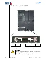
All peripheral grounds are radially merged within the central connector
and placed on the reference ground, the power supply ground (ground
of the aircraft). This ground is the point of reference for all signals,
which are either single ended (GPS or USB) or double-ended as the
serial interface which is connected to ground via peripheral device itself.
Different ground potentials of the devices can cause interference in the best
case – due to strong transients in the worst case permanent damage to the units.
In addition to individual ground strands (mostly signal grounds, part of cables)
the electric shieldings have to be grounded to the aircraft mass due to the
most stable oscillation-free potential.
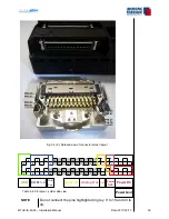
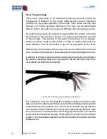
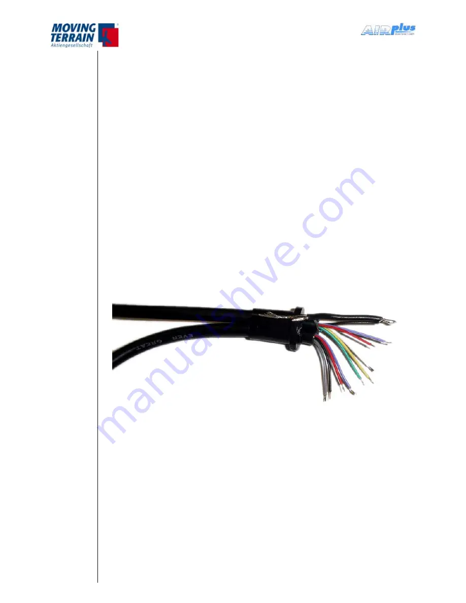
Fig. 5.6.4 (1) Soldering ground strand to unit ground
For metallized connector housings the shielding is placed above the cable
sleeve and on the strain relief. Make sure that the shielding cannot get into
contact with unused connector pins, which can be current-carrying from the
unit. Isolation of the connector pins using a so-called special “Kapton” tape
is recommended. The frame of the connecting plug board itself is connected
to ground in the metallized housing. So the optimum connection to the frame
is given. This guarantees optimal shielding and protection against external
interferences.
Summary of Contents for MT-VisionAir X ETSO
Page 10: ...MTUX IA 63 00 Installation Manual 10 Date 2017 02 17 INTENTIONALLY LEFT BLANK ...
Page 12: ...MTUX IA 63 00 Installation Manual 12 Date 2017 02 17 INTENTIONALLY LEFT BLANK ...
Page 28: ...MTUX IA 63 00 Installation Manual 28 Date 2017 02 17 INTENTIONALLY LEFT BLANK ...
Page 107: ...MTUX IA 63 00 Installation Manual 107 Date 2017 02 1700 12 4 Dimensions in mm ...
Page 112: ...MTUX IA 63 00 Installation Manual 112 Date 2017 02 17 13 3 Dimensions in mm ...
Page 125: ...MTUX IA 63 00 Installation Manual 125 Date 2017 02 1700 INTENTIONALLY LEFT BLANK ...
Page 137: ...MTUX IA 63 00 Installation Manual 137 Date 2017 02 1700 ...
Page 138: ...MTUX IA 63 00 Installation Manual 138 Date 2017 02 17 ...
Page 139: ...MTUX IA 63 00 Installation Manual 139 Date 2017 02 1700 INTENTIONALLY LEFT BLANK ...
Page 146: ...MTUX IA 63 00 Installation Manual 146 Date 2017 02 17 INTENTIONALLY LEFT BLANK ...

