


MTUX/IA-63-00 – Installation Manual
66
Date: 2017/02/17
9.4.3 Installation of modified antenna adapter for Iridium 9555
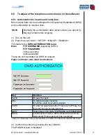
9.4.3.1
Mounting / cable routing
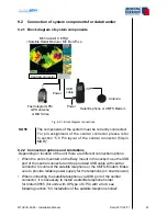
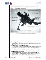
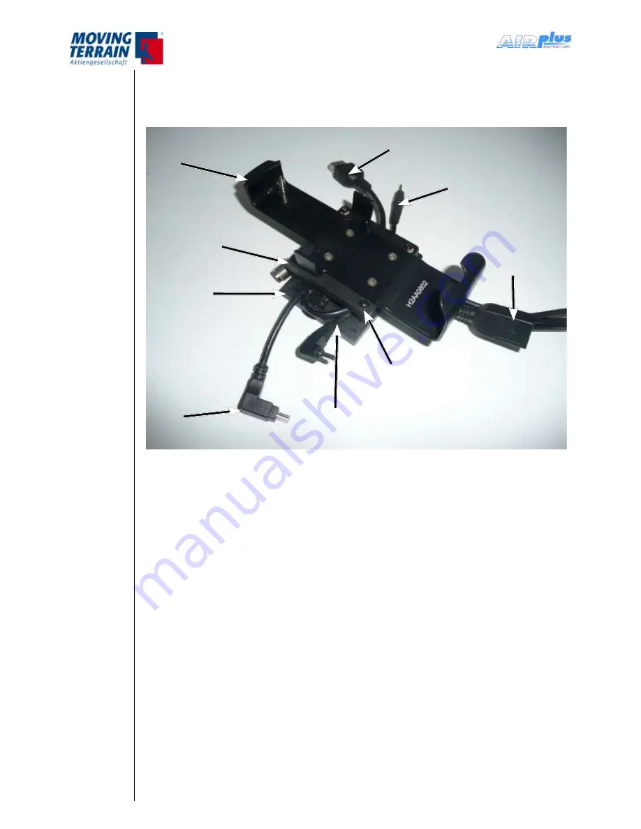
Fig. 9.4.3.1: Parts / Cable routing of satellite telephone holder
1. Mounting of the back plate
Mount the back plate (D) of the holder in the cockpit according to your
specification.
2. Cable routing to the satellite telephone
Lead the power supply cable (A) for the satellite telephone from below
to the left hand side of the holder. Lead the USB cable from MT-Vision-
Air X (B) and the audio cable of the SafetyCell (K) from below to the
right hand side of the holder.
3. Cable routing from satphone
Lead the reserve cable from the USB hub (C) (for the optional 3G
UMTS USB Stick), coming from the left hand side of the integrated
USB hub, to the bottom of the satellite telephone holder.
(G) Cradle
(B) USB from VisionAir X
(K) Audio cable
(C) Reserve
cable from
USB Hub
(F) Connecting screws
(A) Power supply cable
(J) Mini USB plug
(D) Back plate
(E) Front plate
Summary of Contents for MT-VisionAir X ETSO
Page 10: ...MTUX IA 63 00 Installation Manual 10 Date 2017 02 17 INTENTIONALLY LEFT BLANK ...
Page 12: ...MTUX IA 63 00 Installation Manual 12 Date 2017 02 17 INTENTIONALLY LEFT BLANK ...
Page 28: ...MTUX IA 63 00 Installation Manual 28 Date 2017 02 17 INTENTIONALLY LEFT BLANK ...
Page 107: ...MTUX IA 63 00 Installation Manual 107 Date 2017 02 1700 12 4 Dimensions in mm ...
Page 112: ...MTUX IA 63 00 Installation Manual 112 Date 2017 02 17 13 3 Dimensions in mm ...
Page 125: ...MTUX IA 63 00 Installation Manual 125 Date 2017 02 1700 INTENTIONALLY LEFT BLANK ...
Page 137: ...MTUX IA 63 00 Installation Manual 137 Date 2017 02 1700 ...
Page 138: ...MTUX IA 63 00 Installation Manual 138 Date 2017 02 17 ...
Page 139: ...MTUX IA 63 00 Installation Manual 139 Date 2017 02 1700 INTENTIONALLY LEFT BLANK ...
Page 146: ...MTUX IA 63 00 Installation Manual 146 Date 2017 02 17 INTENTIONALLY LEFT BLANK ...