
MTUX/IA-63-00 – Installation Manual
96
Date: 2017/02/17
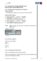
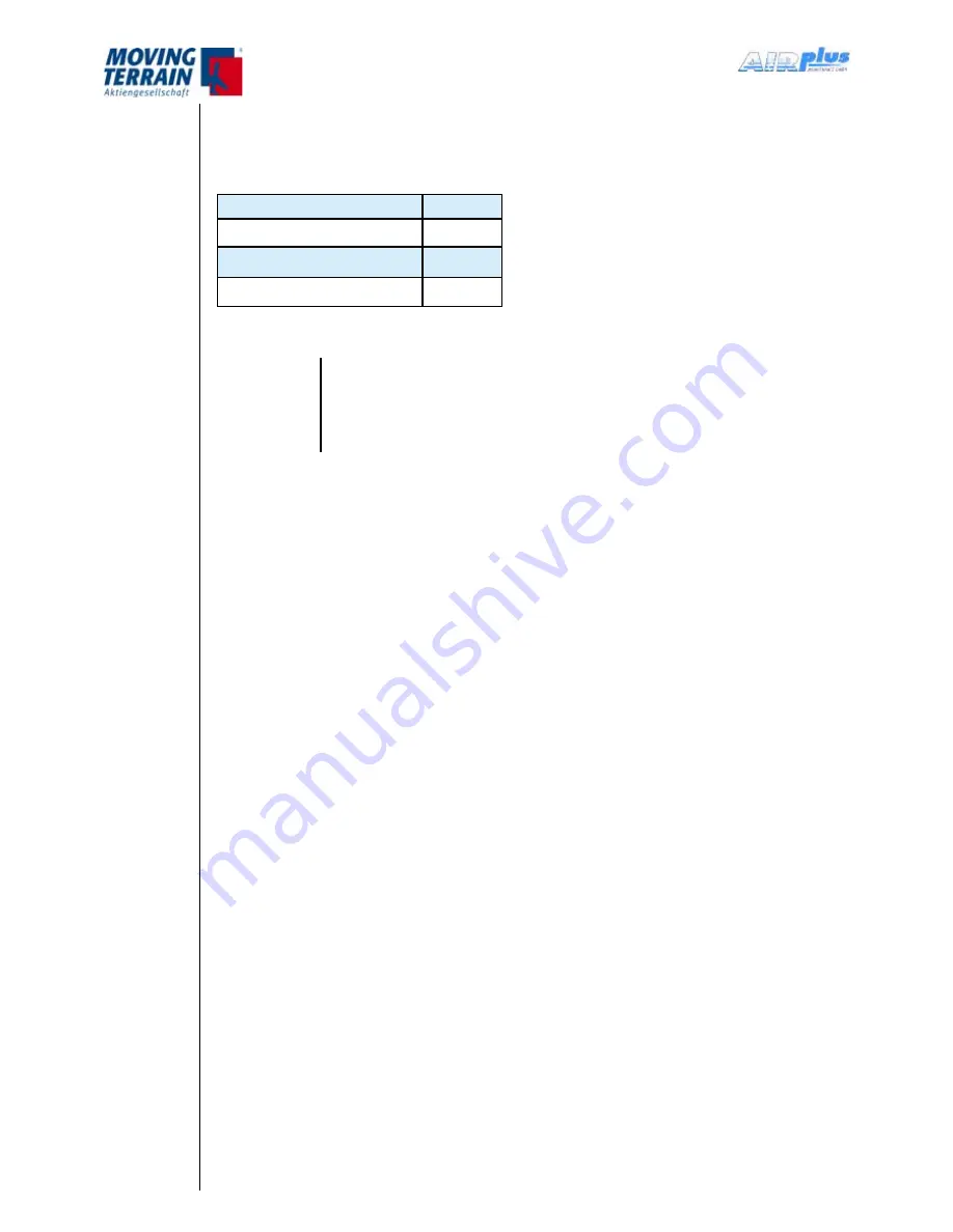
10.1.7 Pin assignment COM 1 port for MT-VisionAir X ETSO devices
For the pin assignment of the serial COM 1 ports (RS232-Port 1) for 50-pin
MDR central connector refer to the following table:
Signal
Pin
COM 1 RxD
45
COM 1 TxD
46
GND COM 1–4
19
Table 10.1.7: Pin assignment COM 1 port
NOTE
If only one TAS source is connected TAS1SEL has to be
used, the output port is COM1. If 2 different TAS sources are
selected, the output port for TAS1SEL is COM1, for TAS2SEL
it is COM3.
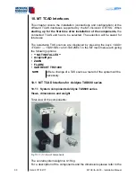
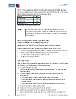
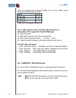
10.1.8 Configuration for the operation of the
Avidyne TAS600 series with Moving Terrain
Display as MFD (Multi-Function Display) without Avidyne display.
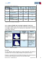
1) Preconditions for the certified operation of the device are:
Annunciator light (labeled “Traffic“ or “Traffic alert“) must be installed.
Mute switch (labeled “Mute/Update”) must be installed.
Feed into the audio system of the aircraft
MFD is optionally certified.
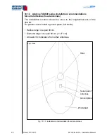
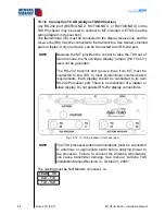
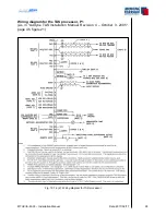
2) Configuration
See “Avidyne TAS Installation Manual Revision 4 – October 3, 2005, page
34, Figure 11: Block Diagram of Electrical Wiring“.
a) 1 switch ON/OFF to GND
Can be replaced with a permanent ground wire and + to the unit (per-
manent power)
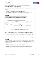
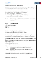
b) 1 switch Mute to GND (warning signal only to be interrupted, not
switched off)
The mute switch must be within easy reach of the pilot.
The mute switch interrupts the optical and acoustic warning for a
certain period.
The mute switch does not turn off the loudspeaker nor the TCAD.
c) 1 switch for annunciator light to GND
d) Connection to the audio system of the aircraft
e) Optional: gear down switch or weight-on-wheel switch
(also works without a gear down/ w.o.w. switch due to recognition of
•
•
•
•
•
•
•
Summary of Contents for MT-VisionAir X ETSO
Page 10: ...MTUX IA 63 00 Installation Manual 10 Date 2017 02 17 INTENTIONALLY LEFT BLANK ...
Page 12: ...MTUX IA 63 00 Installation Manual 12 Date 2017 02 17 INTENTIONALLY LEFT BLANK ...
Page 28: ...MTUX IA 63 00 Installation Manual 28 Date 2017 02 17 INTENTIONALLY LEFT BLANK ...
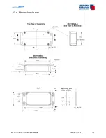
Page 107: ...MTUX IA 63 00 Installation Manual 107 Date 2017 02 1700 12 4 Dimensions in mm ...
Page 112: ...MTUX IA 63 00 Installation Manual 112 Date 2017 02 17 13 3 Dimensions in mm ...
Page 125: ...MTUX IA 63 00 Installation Manual 125 Date 2017 02 1700 INTENTIONALLY LEFT BLANK ...
Page 137: ...MTUX IA 63 00 Installation Manual 137 Date 2017 02 1700 ...
Page 138: ...MTUX IA 63 00 Installation Manual 138 Date 2017 02 17 ...
Page 139: ...MTUX IA 63 00 Installation Manual 139 Date 2017 02 1700 INTENTIONALLY LEFT BLANK ...
Page 146: ...MTUX IA 63 00 Installation Manual 146 Date 2017 02 17 INTENTIONALLY LEFT BLANK ...