C320Turbo/PCIEL
Connection Option and Cable Wiring
5-8
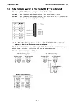
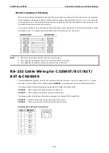
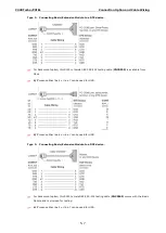
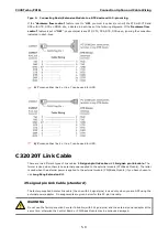
Type 3: Connecting Basic/Extensive Module to a DTE device with 3-pin wiring.
If the “Hardware flow control” feature is set to “ON”, you must loop back (or short) the RTS with CTS and
DSR with DTR, DCD on MOXA site, indicated in dash-lines of the following diagrams. If the“Hardware flow
control” feature is set to “OFF”, you could just leave RTS, CTS, DSR, DTR, DCD open, ignoring the connection
indicated in dash-lines.
☞
4/7 means either line 4 or line 7 can be used for GND.
☞
4/7 means either line 4 or line 7 can be used for GND.
C32020T Link Cable
There are two different types of link cables: 25-signal-pin link cable and 10-signal- pin link cable. The
former is used when there is no external power applied to the external module (CPU/Basic Module). The latter
is used when the external power is applied to the external module (CPU/Basic Module) if you have chosen to
use Long Rang Extension Kit.
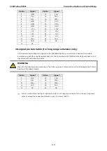
25-signal-pin Link Cable (standard)
The factory-supplied 2-meter link cable (the one with 25 signal pins) is used only when you are NOT using the
external power adapter. Pin assignments are given below for this 25-pin link cable.
WARNING
Do not use the factory-supplied 2-meter link cable (with 25 signal pins) and the external power adapter at the
same time, otherwise the Control Board or CPU/Basic Module may be seriously damaged.

