background image

Universal PCI Board 

Serial Programming Tools 


4-2 

Overview 

Moxa provides Windows serial programming libraries and troubleshooting utilities that are easy to use and 
powerful. You can use these tools to reduce software development time.  

The serial communication library is useful for developing applications for data communications, remote access, 
data acquisition, and industrial control. It provides a simpler solution compared to the more complex Windows 
Win32 COMM API.   

PComm is a professional serial communication tool for Windows PCs. PComm includes the following features: 


Useful utilities for diagnostics, port monitoring, and terminal emulation 


Sample programs 


Comprehensive help files 

Serial Programming Library 

The serial programming library assists you in developing serial communications programs for any COM port 
that complies with the Microsoft Win32 API. It facilitates the implementation of multi-process and multi-thread 
serial communication programs and can remarkably reduce development time. 

The library provides a complete set of functions as well as various sample programs for Visual C++, Visual 
Basic, and Delphi. To view detailed descriptions of the available functions and sample programs, go to Start 


Program 

 PComm Lite and select PComm Lib HelpPComm Porting Notes, or PComm Programming 

Guide. You may also refer to the sample programs in the PComm directory. 

PComm Utilities 

This section provides brief descriptions of the PComm utilities. For more information about these utilities, 
please refer to the Windows help files or to the API-232.txt file for DOS. 

Installation 

To install PComm, run Setup.exe from the Document and Software CD. Please note that the PComm 
diagnostic and monitor utilities are for Moxa boards only. These two utilities will not work with other serial 
boards. 


Summary of Contents for CP-118U Series

Page 1: ...Universal PCI Board User s Manual Multiport Serial Board for PCI and PCI X Bus Ninth Edition December 2012 www moxa com product 2012 Moxa Inc All rights reserved...

Page 2: ...to this manual or to the products and or the programs described in this manual at any time Information provided in this manual is intended to be accurate and reliable However Moxa assumes no responsi...

Page 3: ...it 64 bit 3 11 Windows 2003 XP 3 22 Windows 2000 3 34 Windows NT 3 45 Windows 95 98 ME 3 52 Windows CE 3 61 Non Windows Driver 3 73 DOS 3 73 Linux 32 bit 64 bit 3 77 SCO 3 77 4 Serial Programming Tool...

Page 4: ...5 14 DB44 Female RS 232 Ports 1 and 2 only 5 14 DB44 Female RS 422 5 15 DB44 Female RS 485 4 wire 5 15 DB44 Female RS 485 2 wire 5 16 CP 138U 5 16 DB62 Female RS 422 RS 485 4 wire 5 17 DB62 Female RS...

Page 5: ...1 1 Introduction The following topics are covered in this chapter Overview Applications Package Checklist Product Features Product Specifications Installation Guide...

Page 6: ...114UL I 4 ports RS 232 422 485 low profile 2KV optical isolation CP 114UL I T 4 ports RS 232 422 485 low profile 2KV optical isolation wide temperature CP 134U 4 ports RS 422 485 CP 134U T 4 ports RS...

Page 7: ...write extra code for Windows applications to control the half duplex protocol ADDC intelligence is built into Industio boards Serial over fiber Board The CP 102UF is a serial over fiber board designe...

Page 8: ...l Basic Visual C Borland Delphi and more Utilities are included for debugging monitoring communication status terminal emulation and file transfer Applications UPCI boards are suitable for many indust...

Page 9: ...zed PCs on L models only 2 KV optical isolation protection on I models only 40 to 85 C wide temperature on T models only Product Specifications Hardware I O Controller MU860 compatible with 16C550C Co...

Page 10: ...a Bits 5 6 7 8 Stop Bits 1 1 5 2 I O Address IRQ Assigned by BIOS FIFO 128 bytes Flow Control RTS CTS XON XOFF Driver Support Windows 2012 x64 8 x86 x64 Windows 7 x86 x64 Windows 2000 Windows XP 2003...

Page 11: ...132UL I POS 104UL and CP 102UF For details please refer to Chapter 2 Step 2 Install board UPCI boards are installed in an open PCI or PCI X expansion slot on the PC For details please refer to Chapter...

Page 12: ...apter Overview Configuring the Board and Dimension CP 118U CP 118U I CP 138U CP 138U I CP 168U CP 114UL CP 114UL I CP 134U CP 134U I CP 104UL CP 104JU POS 104UL CP 112UL CP 112UL I CP 132UL CP 132UL I...

Page 13: ...Since the BIOS automatically assigns the IRQ number and I O addresses you will need to install the board before you install the drivers You can install up to 4 UPCI boards in one system as long as su...

Page 14: ...the jumper pins to activate the termination resistor leave the jumper pins open to bypass the termination resistor The onboard DIP switches S1 S2 and S3 are used to select RS 232 RS 422 or RS 485 mod...

Page 15: ...to serial port 8 7 6 5 4 3 2 1 respectively Short the jumper pins to activate the termination resistor leave the jumper pins open to bypass the termination resistor The onboard DIP switches S1 and S2...

Page 16: ...Universal PCI Board Hardware Installation 2 5 CP 168U This board does not require configuration 4 Ports CP 114UL CP 114UL I...

Page 17: ...jumper pins to activate the termination resistor leave the jumper pins open to bypass the termination resistor The onboard DIP switches S1 S2 and S3 are used to select RS 232 RS 422 or RS 485 mode for...

Page 18: ...4 3 2 1 respectively Short the jumper pins to activate the termination resistor leave the jumper pins open to bypass the termination resistor The onboard DIP switches S1 and S2 are used to select RS 4...

Page 19: ...re Installation 2 8 RS 422 or RS 485 mode Use the jumper to cover the left two columns of jumper pins RS 232 mode Use the jumper to cover the right two columns of jumper pins CP 104UL This board does...

Page 20: ...tom row of jumper pins selects the source of 5V power Bus power External power If 5V or 12V external power is enabled you will need to connect the cable from the back of POS 104UL to the PC s power su...

Page 21: ...nation resistor leave the jumper pins open to bypass the termination resistor The onboard DIP switches S1 S2 and S3 are used to select RS 232 RS 422 or RS 485 mode for each serial port Switch 1 corres...

Page 22: ...serial port 1 Short the jumper pins to activate the termination resistor leave the jumper pins open to bypass the termination resistor The onboard DIP switches S1 and S2 are used to select RS 422 or...

Page 23: ...Universal PCI Board Hardware Installation 2 12 CP 102UL This board does not require configuration CP 102U This board does not require configuration...

Page 24: ...cate with serial devices connected to the ring Note that the Tx port of the CP 102UF connects to a neighboring converter s Rx port to form the ring When one node transmits a signal the signal travels...

Page 25: ...e PC s cover Step 3 Configure the UPCI board s DIP switches and jumpers as necessary This only applies to certain models For additional information please refer to your model in this chapter Step 4 In...

Page 26: ...revious chapter Hardware Installation Refer to the next chapter Serial Programming Tools for information about developing your own serial programming applications Note that you can install up to 4 PCI...

Page 27: ...owing procedure describes how to install the CP 104U driver for the first time with Windows 8 First make sure that you have already plugged the board or boards into the system s PCI or PCI X slot s NO...

Page 28: ...ocation select Include subfolders and then click Browse If the system is a 32 bit x86 platform navigate to the CP 104U Series Software Windows 8 x86 folder on the CD If the system is a 64 bit x64 plat...

Page 29: ...tes that Windows has completed the driver installation Click Close to proceed with the rest of the installation procedure 5 After installing the multiport serial adaptors driver install the Moxa Port...

Page 30: ...ocation select Include subfolders and then click Browse If the system is a 32 bit x86 platform navigate to the CP 104U Series Software Windows 8 x86 folder on the CD If the system is a 64 bit x64 plat...

Page 31: ...er all files have been copied to the system window showing Windows has successfully updated your driver software will open to indicate that it has finished installing MOXA Port 0 The Port installation...

Page 32: ...ng the Ports After the driver has been installed use Device Manager to configure the CP 104U serial ports 1 Expand the Multi port serial adapters tab right click MOXA CP 104U Series PCI Bus and then c...

Page 33: ...Port Setting 3 Select a COM number for the port from the Port Number pull down list Select the Auto Enumerating COM Number option to map subsequent ports automatically The port numbers will be assigne...

Page 34: ...with the default set to High 128 bytes Select Set the change to all ports option to apply the just defined Tx FIFO Size to all ports Tx FIFO Rx FIFO High 128 120 Middle 64 60 Low 1 1 6 Click OK to sa...

Page 35: ...Expand Multi port Serial Adapters tab right click CP 104U Series and then click Uninstall to remove the UPCI driver 3 The Device Manager window refreshes automatically showing that the driver and port...

Page 36: ...boards The drivers conform to the Win32 COMM API standard Installing the Driver The following instructions show how to install the driver for the first time under Windows 2008 Vista You will need to...

Page 37: ...Universal PCI Board Software Installation 3 12...

Page 38: ...Universal PCI Board Software Installation 3 13 2 Select I don t have the disc Show me other options 3 Select Browse my computer for driver software advanced...

Page 39: ...oduct folder in the Software directory e g under CP 118U Series Software For 32 bit x86 platforms select the Windows 2008_Vista x86 folder For 64 bit x64 platforms select the Windows 2008_Vista x64 fo...

Page 40: ...k Close to exit the wizard Installing the Ports After the board and drivers have been installed an installation wizard will guide you through installation of the newly added serial ports starting with...

Page 41: ...on the Document Software CD for the driver Drivers for all operating systems are located under the product folder in the Software directory e g under CP 118U Series Software For 32 bit x86 platforms s...

Page 42: ...warning message stating that the Windows can t verify the publisher of the software select Install this driver software anyway 11 After the drivers have been installed click Close to exit the wizard T...

Page 43: ...Board Software Installation 3 18 Verifying the Installation You can use Windows Device Manager to verify proper installation 1 Under My Computer click System Properties 2 In the System window click D...

Page 44: ...port serial adapters CP 118U in this example You should also see Moxa communication ports under Ports COM LPT 4 If you see any special marks such as a question mark or an exclamation mark next to the...

Page 45: ...numerating COM Number to map subsequent ports in numerical order For example if COM 3 is assigned to Port 1 then COM 4 will be automatically assigned to Port 2 Select an Rx FIFO Trigger and Tx FIFO Si...

Page 46: ...ard 1 Right click My Computer and select Properties in the context menu 2 In the System window click Device Manager 3 In Device Manager right click the UPCI board under Multi port serial adapters and...

Page 47: ...e and select Uninstall in the context menu 4 A confirmation dialog will appear Click OK to uninstall the device Windows 2003 XP This chapter explains how to install configure update and remove the boa...

Page 48: ...board in an available PCI or PCI X slot first before installing the driver ATTENTION The following steps will not be necessary if a Moxa UPCI board was already installed on your computer Windows will...

Page 49: ...in the search Click Browse and select the appropriate directory on the Document Software CD for the driver Drivers for all operating systems are located under the product folder in the Software direct...

Page 50: ...Board Software Installation 3 25 4 If you see a warning that the software has not passed Windows Logo testing click Continue Anyway 5 Windows will install the drivers When the installation is complete...

Page 51: ...Ports After the board and drivers have been installed an installation wizard will guide you through installation of the newly added serial ports starting with port 0 1 When prompted to connect to Wind...

Page 52: ...in the search Click Browse and select the appropriate directory on the Document Software CD for the driver Drivers for all operating systems are located under the product folder in the Software direct...

Page 53: ...8 4 If you see a warning that the software has not passed Windows Logo testing click Continue Anyway 5 After the drivers for the serial port have been installed click Finish to close the wizard Repeat...

Page 54: ...stallation 3 29 Verifying the Installation You can use Windows Device Manager to verify proper installation of the board 1 Right click My Computer and select Properties in the context menu 2 In the Ha...

Page 55: ...der Multi port serial adapters CP 118U in this example You should also see Moxa communication ports under Ports COM LPT 4 If you see any special marks such as a question mark or an exclamation mark ne...

Page 56: ...umerating COM Number to map subsequent ports in numerical order For example if COM 3 is assigned to Port 1 then COM 4 will be automatically assigned to Port 2 3 Select an Rx FIFO Trigger and Tx FIFO S...

Page 57: ...and serial ports are working properly You may download PComm from the Moxa website Using Event Log You may refer to the Windows event log to verify operation of the board To view the event log open Ev...

Page 58: ...er right click the UPCI board under Multi port serial adapters and select Disable in the context menu This will disable the board Uninstalling the Board 1 Right click My Computer and select Properties...

Page 59: ...og will appear Click OK to uninstall the device Windows 2000 This chapter explains how to install configure update and remove the board drivers for Windows 2000 The following models are supported 2 Po...

Page 60: ...r 2 Installing the Driver The following instructions show how to install the driver for the first time under Windows 2000 You will need to plug the board in an available PCI or PCI X slot first before...

Page 61: ...3 Select Specify a location and click Next to continue 4 Click Browse and select the appropriate directory on the Document Software CD for the driver Drivers for all operating systems are located und...

Page 62: ...versal PCI Board Software Installation 3 37 5 After the wizard has located the driver files click Next to proceed 6 If you see a warning that the digital signature has not been found click Yes to proc...

Page 63: ...en the installation is complete click Finish Installing the Ports After the board and drivers have been installed an installation wizard will guide you through installation of the newly added serial p...

Page 64: ...3 Select Specify a location and click Next to continue 4 Click Browse and select the appropriate directory on the Document Software CD for the driver Drivers for all operating systems are located und...

Page 65: ...d 6 After the drivers have been installed click Finish to exit the wizard The other serial ports will automatically install in the background Verifying the Installation You can use Windows Device Mana...

Page 66: ...ee your UPCI board under Multi port serial adapters CP 118U in this example You should also see Moxa communication ports under Ports COM LPT 4 If you see any special marks such as a question mark or a...

Page 67: ...umerating COM Number to map subsequent ports in numerical order For example if COM 3 is assigned to Port 1 then COM 4 will be automatically assigned to Port 2 3 Select an Rx FIFO Trigger and Tx FIFO S...

Page 68: ...and serial ports are working properly You may download PComm from the Moxa website Using Event Log You may refer to the Windows event log to verify operation of the board To view the event log open Ev...

Page 69: ...er right click the UPCI board under Multi port serial adapters and select Disable in the context menu This will disable the board Uninstalling the Board 1 Right click My Computer and select Properties...

Page 70: ...ing prompt click OK to uninstall the device Windows NT This chapter explains how to install configure update and remove the board drivers for Windows NT The following models are supported 2 Ports 4 Po...

Page 71: ...slot first before installing the driver Note that these instructions use the CP 168U as an example The procedure for installing all models is the same 1 Log into Windows NT as Administrator Locate the...

Page 72: ...listed Windows NT does not automatically detect Moxa UPCI boards so you will need to click Add for a newly installed board 4 Under Board Type select the UPCI board that is being installed The window w...

Page 73: ...and System For each newly installed or configured Moxa UPCI board check for a message stating that the board has been enabled e g Moxa CP 168U board with first serial port COM3 has been enabled ATTENT...

Page 74: ...iversal PCI Board Software Installation 3 49 2 The configuration panel will open with a list of installed boards Select your board and click Property Up to 4 Moxa UPCI boards can be installed at a tim...

Page 75: ...bsequent ports in numerical order For example if COM 3 is assigned to Port 1 then COM 4 will be automatically assigned to Port 2 Select an Rx FIFO Trigger and Tx FIFO Size The default Rx FIFO Trigger...

Page 76: ...a board shut of your PC and physically remove the board from the PCI slot The next time you start up the PC Windows NT will automatically remove the configuration You do not need to go through the Win...

Page 77: ...02U CP 104JU CP 102UF POS 104UL Windows 95 98 ME supports up to 128 serial ports from COM1 to COM128 In order to fully utilize the advanced multi process and multi thread features of Windows 95 98 ME...

Page 78: ...indows will automatically detect and install any additional board s at bootup In this case you may proceed directly to configuring the ports Windows 95 1 After the board is physically installed and th...

Page 79: ...directory e g under CP 168U Software Select the Win9x folder and click OK to continue 4 After Windows finds the drivers click Finish 5 You may begin configuring and using the new COM ports right away...

Page 80: ...Universal PCI Board Software Installation 3 55 2 Select Display a list and click Next 3 Select Other Devices and click Next 4 Select Have Disk...

Page 81: ...priate directory on the Document Software CD for the driver Drivers for all operating systems are located under the product folder in the Software directory e g under CP 168U Software Select the Win9x...

Page 82: ...ports after the board and drivers have been installed 1 In the Windows Control Panel open the System applet 2 In the Device Manager tab expand the Moxa Smartio Industio multiport board category by cli...

Page 83: ...lect an Rx FIFO Trigger and Tx FIFO Size The default Rx FIFO Trigger is 120 bytes high level The default Tx FIFO Size is 128 bytes high level Select Set the change to all ports to use this setting for...

Page 84: ...orts after the board and drivers have been installed 1 In the Windows Control Panel open the System applet 2 In the Device Manager tab expand the Moxa Smartio Industio multiport board category by clic...

Page 85: ...prompted select the appropriate directory on the Document Software CD for the driver Drivers for all operating systems are located under the product folder in the Software directory e g under CP 118U...

Page 86: ...urn to the Add Remove Programs applet Windows CE Windows CE 5 0 In this section we explain how to install Moxa Universal PCI boards under WinCE 5 0 These instructions are intended for users who are fa...

Page 87: ...to WINCEROOT PLATFORM automatically and import the supported Moxa Tech products into the Folder 1 Start WinCE Platform Builder select File and open New Platform 2 Enter a Name for Workspace and press...

Page 88: ...Universal PCI Board Software Installation 3 63...

Page 89: ...r Prefix COM or Prefix MXU you would like to include and choose Add to OS Design NOTE You can only select either Prefix COM or Prefix MXU but not both 5 Prefix COM supports up to 10 ports from COM0 to...

Page 90: ...e drivers included in your OS Design NOTE If you would like to use Terminal Emulator tool please modify mxserce5 reg and keyboard like below This is only just for one COM port You have to notice numbe...

Page 91: ...6 0 The following procedure explains how to install the CP 102U multiport serial board driver under WinCE 6 0 1 Obtain a copy of Moxa s WinCE 6 0 driver and extract it to your computer Double click t...

Page 92: ...Universal PCI Board Software Installation 3 67 3 The CE 6 0 OS Design Wizard will start Click Next to get the Board Support Packages page and select CEPC x86 Click Next to continue...

Page 93: ...stallation 3 68 4 On the Design Templates page select your environment PDA Device for example Click Next to continue 5 On the Design Template Variants page select your environment Mobile Handheld for...

Page 94: ...on Media page select your environment NET Compact Framework 2 0 ActiveSync and Quarter VGA Resources Portrait Mode for example Click Next to continue 7 On the Networking Communication page select your...

Page 95: ...Universal PCI Board Software Installation 3 70 8 When the OS Design Project Wizard Complete screen appears click Finish The catalog notification will pop up Click Acknowledge to finish the project...

Page 96: ...top of the screen and select Add Existing Subproject Specify the PCI MSB Mxser driver location with the subproject file mxserce6 pbpxml 10 After the subproject is added you may configure the mxserce6...

Page 97: ...ine the initial COM port number in WinCE but before using this function make sure that the COM port numbers do not conflict 12 Open Build and select Advanced Build Commands and choose Build Sysgen Thi...

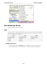
Page 98: ...driver and how to load or unload the driver The following models are supported 2 Ports 4 Ports 8 Ports CP 112UL CP 112UL I CP 114UL CP 114UL I CP 118U CP 118U I CP 132UL CP 132UL I CP 134U CP 134U I...

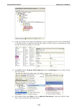
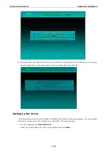
Page 99: ...at you set up the board and driver at this time by pressing Y Setting up the Driver The following instructions are not intended to illustrate every function of the setup program For more detailed info...

Page 100: ...PCI Board Software Installation 3 75 2 Press PgDn to view and modify the setup options for the selected board 3 The settings for each port will be displayed Verify the settings and make any necessary...

Page 101: ...nsmission output buffer allocated in the system for each port RxD buffer size This is the receiving input buffer allocated in the system for each port F5 Group Edit This allows you to configure severa...

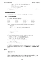
Page 102: ...iv_linux_smart_vx x_build_yymmddhh tgz cd mxser make clean make install cd moxa mxser driver msmknod modprobe mxser If the driver has loaded successfully you should see a message such as the following...

Page 103: ...Enter Confirm Input Value Esc Exit Tab Change Item 5 After rebooting computer key in moxaadm you will see MAIN MENU select Basic Configuration MAIN MENU Basic Configuration Advanced Configuration Int...

Page 104: ...Universal PCI Board Software Installation 3 79 8 Next press Esc to exit and reboot your computer 9 Note whenever you change a MAIN MENU item you have to reboot your computer...

Page 105: ...4 4 Serial Programming Tools The following topics are covered in this chapter Overview Serial Programming Library PComm Utilities Installation PComm Diagnostic PComm Monitor PComm Terminal Emulator...

Page 106: ...rams for any COM port that complies with the Microsoft Win32 API It facilitates the implementation of multi process and multi thread serial communication programs and can remarkably reduce development...

Page 107: ...n of both software and hardware To run the Diagnostic program go to Start Program PComm Lite Diagnostic PComm Monitor PComm Monitor is designed for Moxa boards in Windows NT only It allows you to moni...

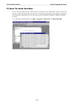
Page 108: ...verify that data transmission is functioning correctly It supports multiple windows and both VT100 and ANSI terminal types You can interactively transfer data periodically send patterns and transfer...

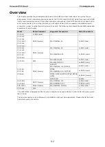
Page 109: ...RS 422 RS 485 4 wire DB62 Female RS 485 2 wire CP 118U I DB78 Female RS 232 DB78 Female RS 422 RS 485 4 wire DB78 Female RS 485 2 wire CP 132UL CP 132UL I DB25 Female RS 422 DB25 Female RS 485 4 wire...

Page 110: ...U 2 DB9 male CP 102UL CP 112UL CP 112UL I CP 132UL CP 132UL I DB25 female CBL M25M9x2 50 2 DB9 male CP 104UL CP 114UL CP 114UL I CP 134U CP 134U I DB44 female CBL M44M9x4 50 4 DB9 male CBL M44M25x4 50...

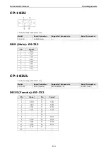
Page 111: ...al 1 DCD 2 RxD 3 TxD 4 DTR 5 GND 6 DSR 7 RTS 8 CTS CP 102UL This board supports RS 232 only Model Board Connector Supported Accessories Serial Connectors CP 102UL DB25 female CBL M25M9x2 50 2 DB9 male...

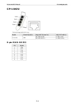
Page 112: ...04JU This board supports RS 232 only Model Board Connector Supported Accessories Serial Connectors CP 104JU RJ45 CBL RJ45M9 150 4 DB9 male CBL RJ45M25 150 4 DB25 male 8 pin RJ45 RS 232 Pin Signal 1 DS...

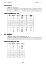
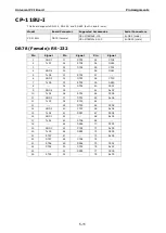
Page 113: ...5 DCD2 6 RxD2 21 DTR2 36 7 RTS2 22 DSR2 37 GND 8 23 38 9 TxD1 24 CTS1 39 DCD1 10 RxD1 25 DTR1 40 11 RTS1 26 DSR1 41 GND 12 27 42 DCD0 13 TxD0 28 CTS0 43 14 RxD0 29 DTR0 44 GND 15 RTS0 30 DSR0 CP 112UL...

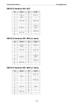
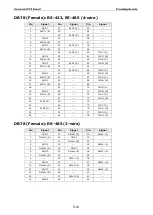
Page 114: ...ND0 10 23 11 24 TxD0 B 12 RxD0 B 25 13 DB25 Female RS 485 4 wire Pin Signal Pin Signal 1 14 2 TxD1 A 15 RxD1 A 3 GND1 16 4 17 5 TxD1 B 18 RxD1 B 6 19 7 20 8 21 TxD0 A 9 RxD0 A 22 GND0 10 23 11 24 TxD0...

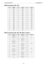
Page 115: ...18 DSR3 33 GND 4 19 34 5 TxD2 20 CTS2 35 DCD2 6 RxD2 21 DTR2 36 7 RTS2 22 DSR2 37 GND 8 23 38 9 TxD1 24 CTS1 39 DCD1 10 RxD1 25 DTR1 40 11 RTS1 26 DSR1 41 GND 12 27 42 DCD0 13 TxD0 28 CTS0 43 14 RxD0...

Page 116: ...26 41 GND 12 27 42 13 Data0 B 28 43 14 29 Data0 A 44 GND 15 30 CP 118U This board supports RS 232 RS 422 and RS 485 both 2 and 4 wire Model Board Connector Supported Accessories Serial Connectors CP...

Page 117: ...7 RTS5 16 RxD6 37 DCD5 58 GND 17 DSR6 38 TxD6 59 CTS6 18 DCD6 39 DTR6 60 RTS6 19 RxD7 40 GND 61 CTS7 20 DSR7 41 TxD7 62 RTS7 21 DCD7 42 DTR7 DB62 Female RS 422 RS 485 4 wire Pin Signal Pin Signal Pin...

Page 118: ...3 2 Data0 A 23 44 3 24 45 GND 4 25 Data1 B 46 5 26 Data1 A 47 6 Data2 B 27 48 7 Data2 A 28 49 8 29 50 GND 9 30 Data3 B 51 10 31 Data3 A 52 11 32 GND 53 12 33 Data4 B 54 13 34 Data4 A 55 GND 14 Data5 B...

Page 119: ...TS2 2 TxD7 28 RTS4 54 DSR2 3 29 DTR4 55 CTS1 4 GND6 30 56 DSR1 5 TxD6 31 RTS3 57 6 GND5 32 DTR3 58 CTS0 7 TxD5 33 RTS2 59 DSR0 8 34 DTR2 60 DCD7 9 GND4 35 61 RxD7 10 TxD4 36 RTS1 62 DCD6 11 GND3 37 DT...

Page 120: ...B 15 RxD2 B 41 67 TxD4 A 16 GND1 42 68 TxD4 B 17 RxD1 B 43 69 18 44 70 TxD3 A 19 GND0 45 71 TxD3 B 20 RxD0 B 46 72 TxD2 A 21 47 73 TxD2 B 22 RxD7 A 48 74 23 49 75 TxD1 A 24 RxD6 A 50 76 TxD1 B 25 51...

Page 121: ...50 2 DB9 male DB25 Female RS 422 Pin Signal Pin Signal 1 14 CTS1 A 2 TxD1 A 15 RxD1 A 3 GND1 16 RTS1 A 4 CTS1 B 17 RTS1 B 5 TxD1 B 18 RxD1 B 6 19 7 20 8 CTS0 A 21 TxD0 A 9 RxD0 A 22 GND0 10 RTS0 A 23...

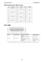
Page 122: ...wire Ports 1 and 2 also support RS 232 Model Board Connector Supported Accessories Serial Connectors CP 134U CP 134U I DB44 female CBL M44M9x4 50 4 DB9 male CBL M44M25x4 50 4 DB25 male DB44 Female RS...

Page 123: ...24 CTS1 B 39 TXD1 A 10 TXD1 B 25 RXD1 A 40 CTS1 A 11 RTS1 B 26 RTS1 A 41 GND1 12 27 42 TXD0 A 13 RXD0 B 28 CTS0 B 43 CTS0 A 14 TXD0 B 29 RXD0 A 44 GND0 15 RTS0 B 30 RTS0 A DB44 Female RS 485 4 wire P...

Page 124: ...GND2 8 23 38 9 Data1 B 24 39 10 25 Data1 A 40 11 26 41 GND1 12 27 42 13 Data0 B 28 43 14 29 Data0 A 44 GND0 15 30 CP 138U This board supports RS 422 and RS 485 both 2 and 4 wire Model Board Connector...

Page 125: ...4 A 55 GND 14 RxD5 B 35 TxD5 B 56 15 RxD5 A 36 57 16 TxD6 B 37 TxD5 A 58 GND 17 38 RxD6 B 59 18 TxD6 A 39 RxD6 A 60 19 TxD7 B 40 GND 61 20 41 RxD7 B 62 21 TxD7 A 42 RxD7 A DB62 Female RS 485 2 wire Pi...

Page 126: ...Pin Signal 1 GND7 27 RxD5 A 53 2 RxD7 B 28 54 3 29 RxD4 A 55 4 GND6 30 56 5 RxD6 B 31 57 6 GND5 32 RxD3 A 58 7 RxD5 B 33 59 8 34 RxD2 A 60 TxD7 A 9 GND4 35 61 TxD7 B 10 RxD4 B 36 62 TxD6 A 11 GND3 37...

Page 127: ...a4 B 24 Data6 A 38 11 GND3 25 39 Data0 A 12 Data3 B 26 40 13 27 Data5 A 41 14 GND2 28 42 CP 168U This board supports RS 232 With the OPT8F or OPT8Z accessory it can support RS 422 With the OPT8K or OP...

Page 128: ...CD5 58 GND 17 DSR6 38 TxD6 59 CTS6 18 DCD6 39 DTR6 60 RTS6 19 RxD7 40 GND 61 CTS7 20 DSR7 41 TxD7 62 RTS7 21 DCD7 42 DTR7 POS 104UL This board supports RS 232 only Model Board Connector Supported Acce...

Page 129: ...le 4 DB9 male CBL RJ45M9 150 RJ45 4 DB9 male OPT8 M9 CBL M62M9x8 100 OPT8D DB62 female 8 DB9 male CBL M78M9x8 100 DB78 female 8 DB9 male The pin assignments for the DB9 male serial connector are shown...

Page 130: ...for the DB25 male serial connector are shown below There are different pin assignments depending on the serial interface that your board is configured for Pin RS 232 RS 422 RS 485 4W RS 485 2W 2 TxD R...

Page 131: ...D GND 8 DCD TxD A 20 DSR OPT8F OPT8Z OPT8K OPT8I Pin RS 422 RS 485 4W RS 485 2W 2 RxD B Data B 3 TxD B 7 GND GND 14 RxD A Data A 16 TxD A RJ45 The following accessories provide RJ45 serial connectors...

Reviews: