Universal PCI Board
Hardware Installation
2-7
CP-134U/CP-134U-I
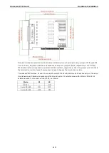
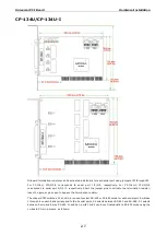
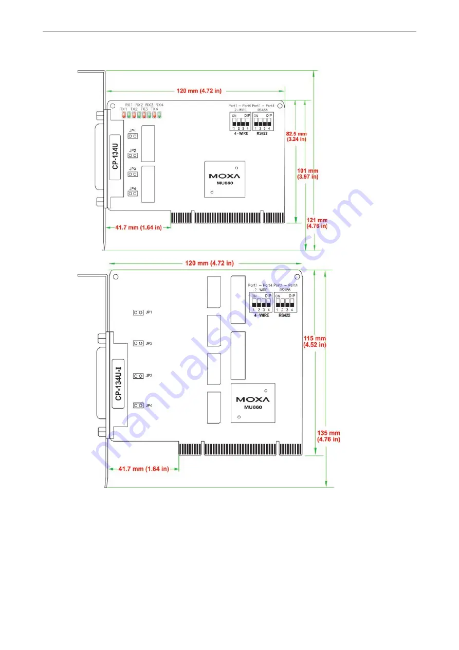
Onboard termination resistors can be activated individually for each serial port using jumpers JP1 through JP4.
For CP-134U, JP1/2/3/4 corresponds to serial port 1/2/3/4, respectively. For CP-134U-I, JP1/2/3/4
corresponds to serial port 4/3/2/1, respectively. Short the jumper pins to activate the termination resistor;
leave the jumper pins open to bypass the termination resistor.
The onboard DIP switches, S1 and S2, are used to select RS-422 or RS-485 mode for each serial port. Switches
1 through 4 on each bank correspond to the 4 serial ports. S2 selects between RS-422 and RS-485; S1 selects
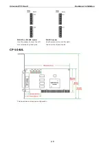
between 2-wire and 4-wire RS-485. In addition, ports 1 and 2 can be set individually to RS-232 mode using the
on-board 30-pin jumpers, as follows:


