background image


P/N: 1802040140110 

*1802040140110* 

EDS-G4014 Series   

Quick Installation Guide 

Moxa EtherDevice™ Switch 

Version 1.0, March 2022 

Technical Support Contact Information 

www.moxa.com/support 


 2022 Moxa Inc. All rights reserved. 


Summary of Contents for EDS-G4014 Series

Page 1: ...2040140110 1802040140110 EDS G4014 Series Quick Installation Guide Moxa EtherDevice Switch Version 1 0 March 2022 Technical Support Contact Information www moxa com support 2022 Moxa Inc All rights re...

Page 2: ...ads on the relevant product pages located on Moxa s website www moxa com Default Settings IP address 192 168 127 253 Subnet Mask 255 255 255 0 Username admin Password moxa Panel Views of EDS G4014 Ser...

Page 3: ...switches for Turbo Ring Ring Master and Ring Coupler Mounting Dimensions DIN rail Mounting The DIN rail mounting kit is fixed to the back panel of the EDS device when you take it out of the box Mount...

Page 4: ...he EDS device forward and lift up to remove it from the DIN rail NOTE Our DIN rail kit now utilizes a quick release mechanism to make it easier for users to remove the DIN rail from the EDS device Wal...

Page 5: ...ow room for sliding the wall mount panel between the wall and the screws STEP 3 Once the screws are fixed to the wall insert the four screw heads through the wide parts of the keyhole shaped apertures...

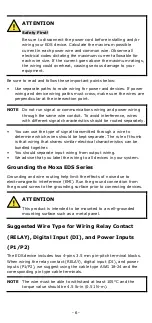
Page 6: ...ough a wire to determine which wires should be kept separate The rule of thumb is that wiring that shares similar electrical characteristics can be bundled together You should separate input wiring fr...

Page 7: ...relay output This relay contact uses two contacts of the terminal block on the EDS s power module Refer to the section for detailed instructions on how to connect the wires to the terminal block conne...

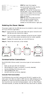
Page 8: ...into the V V or L N terminals respectively STEP 2 To keep the DC or AC wires from pulling loose use a small flat blade screwdriver to tighten the wire clamp screws on the front of the terminal block c...

Page 9: ...e power module clockwise so that the power digital input and relay output connectors can be moved upwards Step 3 Replace the module back on to the EDS device Step 4 Fasten two screws on to the module...

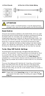
Page 10: ...ch must use 1G or 2 5G mini GBIC fiber transceivers to work properly The concept behind the LC port and cable is quite straightforward Suppose that you are connecting devices I and II contrary to elec...

Page 11: ...to reboot the device by depressing the reset button for less than five seconds Turbo Ring DIP Switch Settings The EDS devices are plug and play managed redundant Ethernet switches The proprietary Tur...

Page 12: ...bled NOTE You must enable the Turbo Ring DIP switch 5 first before using the DIP switch to activate the Master and Coupler functions NOTE If you do not enable any of the EDS switches to be the Ring Ma...

Page 13: ...power input PWR Off Power is not being supplied to power input PWR MSTR HEAD M H Green On When the switch is Master Head Root of Turbo Ring Turbo Chain Fast RSTP Blinking 4 times sec 1 The switch has...

Page 14: ...the port is active and links at 1000Mbps Blinking 4 times sec When the port s data is being transmitted at 1000Mbps Off When the port is inactive or link down 10M 100M 1000M Copper bottom LED Amber O...

Page 15: ...14 HV T Rated Voltage LV LV T models 12 24 48 VDC redundant dual inputs HV HV T models 110 220 VDC VAC single input Operating Voltage LV LV T models 9 6 to 60 VDC HV HV T models 88 to 300 VDC 85 to 26...

Page 16: ...000 4 3 RS Level 3 EN 61000 4 4 EFT Level 4 EN 61000 4 5 Surge Level 4 EN 61000 4 6 CS Level 3 EN 61000 4 8 Level 4 Shock IEC 60068 2 27 Free Fall IEC 60068 2 32 Vibration IEC 60068 2 6 Rail Traffic W...

Reviews: