background image


- 6 -

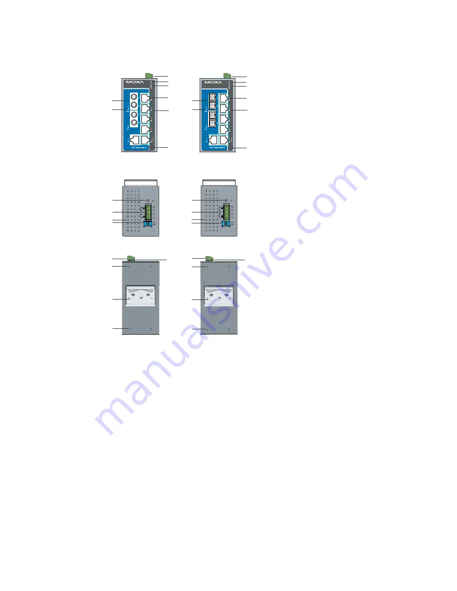
Panel Layout of EDS-208A-MM-SC/ST 

Top Panel View

2

1

Rear Panel View

13

12

12

EDS-208A-MM-SC
Front Panel View

Top Panel View

1

Rear Panel View

2

13

12

12

EDS-208A-MM-ST

Front Panel View

1

2

3
4

1

2

3
4

10

11

5
6

7

8

9

2

5
6

7

8

9

2

10

11

NOTE:


The appearance of 

EDS-208A-SS-SC is 

identical to 

EDS-208A-MM-SC. 


1. Grounding 

screw 

2. 

Terminal block for 

power input P1/P2 

3. Heat 

dissipation 

orifices 

4. DIP 

Switches 

5. 

Power input P1 LED 

6. 

Power input P2 LED 

7. 10/100BaseT(X) 

Port

8. 

TP port’s 10/100 

Mbps LED 

9. Model 

Name 

10. 100BaseFX Port 

11.  FX port’s 100 Mbps 

LED 

12.  Screw hole for wall 

mounting kit 

13. DIN-Rail Kit 


Summary of Contents for EtherDevice EDS-205A series

Page 1: ...Moxa EtherDevice Switch EDS 205A 208A Series Hardware Installation Guide Fourth Edition October 2009 2009 Moxa Inc All rights reserved Reproduction without permission is prohibited P N 1802002050023 ...

Page 2: ... mounting capability and IP30 metal housing with LED indicators make the plug and play EDS 205A 208A switches reliable and easy to use NOTE Throughout this Hardware Installation Guide we use EDS as an abbreviation for Moxa EtherDevice Switch EDS Moxa EtherDevice Switch Package Checklist Your EDS is shipped with the following items If any of these items is missing or damaged please contact your cus...

Page 3: ...208A Front Panel View 5 8 8 6 9 7 EDS 205A Front Panel View 7 2 3 2 1 4 1 2 4 3 1 Grounding screw 2 Terminal block for power input P1 P2 3 Heat dissipation orifices 4 DIP Switches 5 Power input P1 LED 6 Power input P2 LED 7 10 100BaseT X Port 8 TP port s 10 100 Mbps LED 9 Model Name 10 Screw hole for wall mounting kit 11 DIN Rail Kit ...

Page 4: ... 4 5 6 2 5 6 8 7 11 11 8 7 10 10 9 9 NOTE The appearance of EDS 205A S SC is identical to EDS 205A M SC 1 Grounding screw 2 Terminal block for power input P1 P2 3 Heat dissipation orifices 4 DIP Switches 5 Power input P1 LED 6 Power input P2 LED 7 10 100BaseT X Port 8 TP port s 10 100 Mbps LED 9 Model Name 10 100BaseFX Port 11 FX port s 100 Mbps LED 12 Screw hole for wall mounting kit 13 DIN Rail ...

Page 5: ...ew 5 6 7 8 9 10 11 2 1 2 3 4 1 2 3 4 NOTE The appearance of EDS 208A S SC is identical to EDS 208A M SC 1 Grounding screw 2 Terminal block for power input P1 P2 3 Heat dissipation orifices 4 DIP Switches 5 Power input P1 LED 6 Power input P2 LED 7 10 100BaseT X Port 8 TP port s 10 100 Mbps LED 9 Model Name 10 100BaseFX Port 11 FX port s 100 Mbps LED 12 Screw hole for wall mounting kit 13 DIN Rail ...

Page 6: ... 10 11 5 6 7 8 9 2 5 6 7 8 9 2 10 11 NOTE The appearance of EDS 208A SS SC is identical to EDS 208A MM SC 1 Grounding screw 2 Terminal block for power input P1 P2 3 Heat dissipation orifices 4 DIP Switches 5 Power input P1 LED 6 Power input P2 LED 7 10 100BaseT X Port 8 TP port s 10 100 Mbps LED 9 Model Name 10 100BaseFX Port 11 FX port s 100 Mbps LED 12 Screw hole for wall mounting kit 13 DIN Rai...

Page 7: ... 7 Mounting Dimensions unit mm ...

Page 8: ...shown in the following figures STEP 1 Remove the aluminum DIN Rail attachment plate from the EDS 205A 208A s rear panel and then attach the wall mount plates as shown in the diagram at the right top plate bottom plate STEP 2 Mounting the EDS 205A 208A on the wall requires 4 screws Use the switch with wall mount plates attached as a guide to mark the correct locations of the 4 screws The heads of t...

Page 9: ...re Observe all electrical codes dictating the maximum current allowable for each wire size If the current goes above the maximum ratings the wiring could overheat causing serious damage to your equipment You should also pay attention to the following points y Use separate paths to route wiring for power and devices If power wiring and device wiring paths must cross make sure the wires are perpendi...

Page 10: ...de screwdriver to tighten the wire clamp screws on the front of the terminal block connector STEP 3 Insert the plastic terminal block connector prongs into the terminal block receptor which is located on EDS s top panel ATTENTION Before connecting the EtherDevice Switch to the AC DC power inputs make sure the AC DC power source voltage is stable Communication Connections The EDS 205A models have 4...

Page 11: ...behind the SC ST port and cable is quite straightforward Suppose you are connecting devices I and II contrary to electrical signals optical signals do not require a circuit in order to transmit data Consequently one of the optical lines is used to transmit data from device I to device II and the other optical line is used transmit data from device II to device I for full duplex transmission Rememb...

Page 12: ...ource fails the other live source acts as a backup and automatically supplies all of the EDS s power needs DIP Switch Settings EDS 205A 208A DIP Switches ON 1 2 The default setting for each DIP Switch is OFF The following table explains the effect of setting the DIP Switches to the ON positions DIP Switch Setting Description Serves no function reserved for future use ON Enables broadcast storm pro...

Page 13: ...switched RJ45 port auto negotiates with the connected device for the fastest data transmission rate supported by both devices All models of Moxa EtherDevice Switch are plug and play devices so that software configuration is not required at installation or during maintenance The half full duplex mode for the switched RJ45 ports is user dependent and changes by auto negotiation to full or half duple...

Page 14: ...n speeds with the device at the other end of the cable expected to advertise in a similar manner Depending on what type of device is connected this will result in agreement to operate at a speed of either 10 Mbps or 100 Mbps If an EDS RJ45 Ethernet port is connected to a non negotiating device it will default to 10 Mbps speed and half duplex mode as required by the IEEE 802 3u standard Specificati...

Page 15: ...Installation DIN Rail Mounting Wall Mounting with optional kit Environmental Limits Operating Temperature 10 to 60 C 14 to 140 F 40 to 75 C 40 to 167 F for T models Storage Temperature 40 to 85 C 40 to 185 F Ambient Relative Humidity 5 to 95 non condensing Regulatory Approvals Safety UL508 pending Hazardous Location UL cUL Class I Division 2 Groups A B C and D ATEX Class I Zone 2 Ex nC nL IIC T4 P...

Page 16: ...Moxa Americas Toll free 1 888 669 2872 Tel 1 714 528 6777 Fax 1 714 528 6778 Moxa Europe Tel 49 89 3 70 03 99 0 Fax 49 89 3 70 03 99 99 Moxa Asia Pacific Tel 886 2 8919 1230 Fax 886 2 8919 1231 Moxa China Beijing office Tel 86 10 6872 3959 60 61 Fax 86 10 6872 3958 ...

Reviews: