background image


 8 


Grounding MOXA EtherDevice Switch 

Grounding and wire routing help limit the effects of noise due to electromagnetic interference 
(EMI). Run the ground connection from the ground screw to the grounding surface prior to 
connecting devices. 

ATTENTION 


This product is intended to be mounted to a well-grounded mounting surface, such as a metal 

panel. 


Wiring the Alarm Contact 

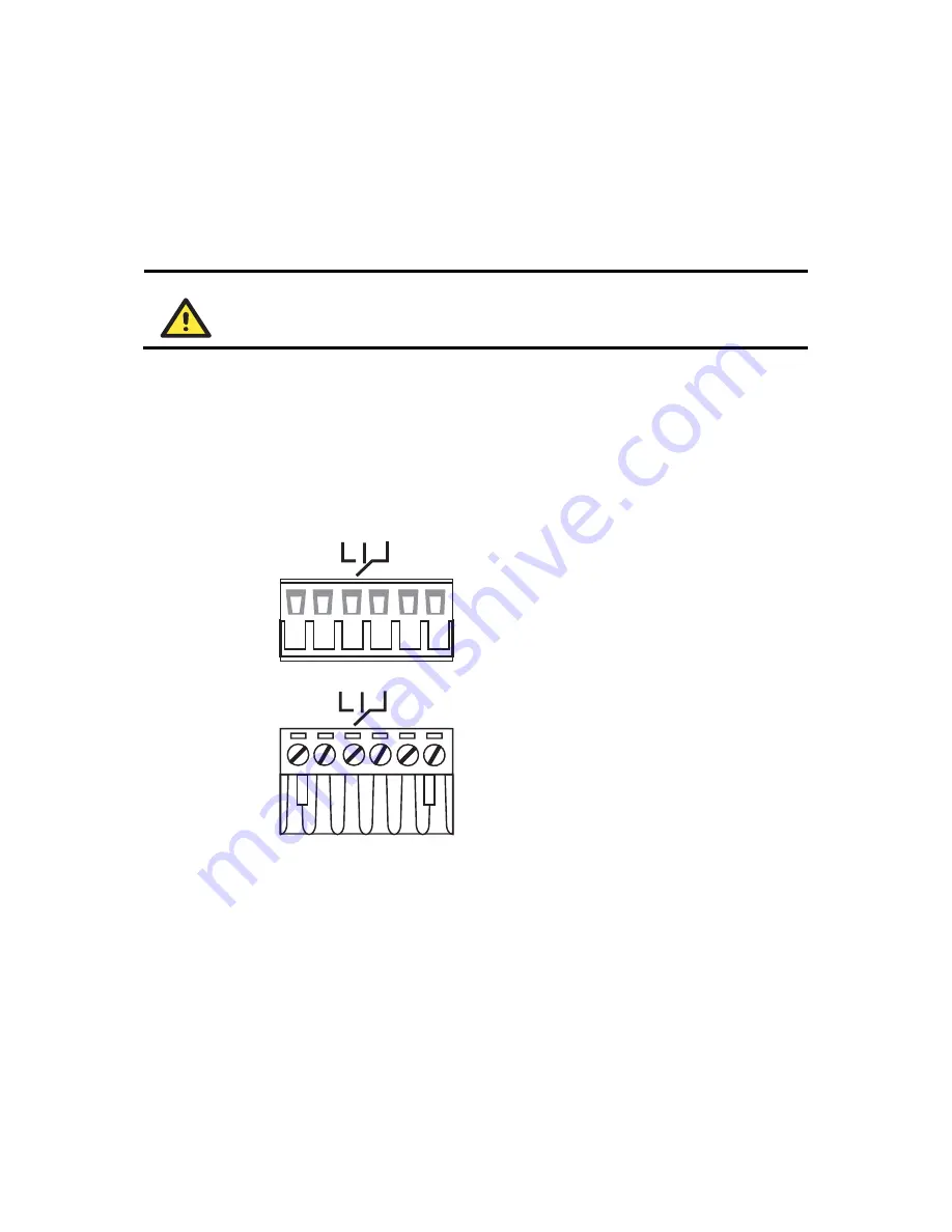
The Alarm Contact consists of the two middle contacts of the terminal block on EDS’s top panel. 
You may refer to the next section for detailed instructions on how to connect the wires to the 
terminal block connector, and how to attach the terminal block connector to the terminal block 
receptor. 

In this section, we explain the meaning of the two contacts used to connect the Alarm Contact. 

FAULT

FAULT

Top View

Front View


FAULT

: The two middle contacts of the 6-contact 

terminal block connector are used to detect both 
power faults and port faults. The two wires 
attached to the Fault contacts form an open circuit 
when: 

1.


EDS has lost power from one of the DC power 
inputs. 
 OR 

2.


One of the ports for which the corresponding 
PORT ALARM DIP Switch is set to ON is not 
properly connected.


If neither of these two conditions is satisfied, the 
Fault circuit will be closed.


Summary of Contents for ETHERDEVICE EDS-305

Page 1: ...ch EDS 308 305 Hardware Installation Guide Fourth Edition September 2004 Moxa Networking Co Ltd Tel 886 2 8919 1230 Fax 886 2 8919 1231 www moxa com support moxanet tw Worldwide support moxa com The Americas P N 18020030003 ...

Page 2: ...e EDS as an abbreviation for MOXA EtherDevice Switch EDS MOXA EtherDevice Switch Package Checklist MOXA EtherDevice Switch is shipped with the following items If any of these items is missing or damaged please contact your customer service representative for assistance MOXA EtherDevice Switch Hardware Installation Guide MOXA Product Warranty booklet Protective caps for unused ports Features High P...

Page 3: ... FAULT PWR1 Top Panel View 1 2 3 4 1 Rear Panel View 2 15 14 14 1 Grounding screw 2 Terminal block for power input P1 P2 and relay output 3 Heat dissipation orifices 4 DIP switches 5 Power input P1 LED 6 Power input P2 LED 7 Fault LED 8 10 100BaseT X Port 9 TP port s 100 Mbps LED 10 TP port s 10 Mbps LED 11 Model Name 12 100BaseFX Port 13 FX port s 100 Mbps LED 14 Screw hole for wall mounting kit ...

Page 4: ...4 14 NOTE The appearance of EDS 308 S SC is identical to EDS 308 M SC and the appearance of EDS 308 MM SC is identical to EDS 308 SS SC 1 Grounding screw 2 Terminal block for power input P1 P2 and relay output 3 Heat dissipation orifices 4 DIP switches 5 Power input P1 LED 6 Power input P2 LED 7 Fault LED 8 10 100BaseT X Port 9 TP port s 100 Mbps LED 10 TP port s 10 Mbps LED 11 Model Name 12 100Ba...

Page 5: ...nit mm Side View 135 00 30 00 9 50 54 00 Back View Front View 10 65 10 65 30 50 9 75 13 90 5 10 10 26 6 Panel Mount Kit 135 00 13 10 15 10 25 40 13 90 18 20 25 71 23 15 7 75 30 50 7 75 3 50 6 00 3 50 6 00 39 37 46 77 13 18 13 ...

Page 6: ...late to EDS make sure the stiff metal spring is situated towards the top as shown in the figures below STEP 1 Insert the top of the DIN Rail into the slot just below the stiff metal spring STEP 2 The DIN Rail attachment unit will snap into place as shown below metal spring DIN Rail metal spring DIN Rail To remove MOXA EtherDevice Switch from the DIN Rail simply reverse Steps 1 and 2 above ...

Page 7: ...he screws should be less than 6 0 mm in diameter and the shafts should be less than 3 5 mm in diameter as shown in the figure at the right NOTE Before tightening screws into the wall make sure the screw head and shank size are suitable by inserting the screw into one of the keyhole shaped apertures of the Wall Mounting Plates Do not screw the screws in all the way leave about 2 mm to allow room fo...

Page 8: ...nt the equipment enclosing the unit must comply with fire enclosure regulation IEC 60950 EN60950 or similar regulation ATTENTION Safety First Be sure to disconnect the power cord before installing and or wiring your MOXA EtherDevice Switch Calculate the maximum possible current in each power wire and common wire Observe all electrical codes dictating the maximum current allowable for each wire siz...

Page 9: ...structions on how to connect the wires to the terminal block connector and how to attach the terminal block connector to the terminal block receptor In this section we explain the meaning of the two contacts used to connect the Alarm Contact FAULT FAULT Top View Front View FAULT The two middle contacts of the 6 contact terminal block connector are used to detect both power faults and port faults T...

Page 10: ...ront View STEP 1 Insert the negative positive DC wires into the V V terminals STEP 2 To keep the DC wires from pulling loose use a small flat blade screwdriver to tighten the wire clamp screws on the front of the terminal block connector STEP 3 Insert the plastic terminal block connector prongs into the terminal block receptor which is located on EDS s top panel ATTENTION Before connecting EDS to ...

Page 11: ...DI X HUB Switch type ports and also show cable wiring diagrams for straight through and cross over Ethernet cables MDI Port Pinouts MDI X Port Pinouts 8 pin RJ45 Pin Signal Pin Signal 1 Tx 1 Rx 2 Tx 2 Rx 3 Rx 3 Tx 6 Rx 6 Tx RJ45 8 pin to RJ45 8 pin Straight Through Cable Wiring Straight Through Cable RJ45 Plug Pin 1 Switch Port RJ45 Connector RJ45 Connector Tx Tx Rx Rx NIC Port Cable Wiring 3 3 6 ...

Page 12: ...ge to your eyes do not stare directly into the Laser Beam Redundant Power Inputs Both power inputs can be connected simultaneously to live DC power sources If one power source fails the other live source acts as a backup and automatically supplies all of MOXA EtherDevice Switch s power needs Alarm Contact MOXA EtherDevice Switch has one Alarm Contact located on the top panel For detailed instructi...

Page 13: ... input P1 P1 AMBER Off Power is not being supplied to power input P1 On Power is being supplied to power input P2 P2 AMBER Off Power is not being supplied to power input P2 On When the corresponding PORT alarm is enabled and the port s link is inactive Fault RED Off When the corresponding PORT alarm is enabled and the port s link is active or when the corresponding PORT alarm is disabled On TP por...

Page 14: ...ll models of MOXA EtherDevice Switch are plug and play devices so that software configuration is not required at installation or during maintenance The half full duplex mode for the switched RJ45 ports is user dependent and changes by auto negotiation to full or half duplex depending on which transmission speed is supported by the attached device Switching Filtering and Forwarding Each time a pack...

Page 15: ...t type of device is connected this will result in agreement to operate at a speed of either 10 Mbps or 100 Mbps If a MOXA EtherDevice Switch RJ45 Ethernet port is connected to a non negotiating device it will default to 10 Mbps speed and half duplex mode as required by the IEEE 802 3u standard Specifications Technology Standards IEEE802 3 802 3u 802 3x Forward and Filtering Rate 148810 pps Packet ...

Page 16: ...ight 0 63 kg Installation DIN Rail Wall Mounting Environmental Operating Temperature 0 to 60oC 32 to 140oF 40 to 75oC 40 to 167oF for T models Storage Temperature 40 to 85oC 40 to 185oF Ambient Relative Humidity 5 to 95 non condensing Regulatory Approvals Safety UL60950 UL 508 CSA C22 2 No 60950 EN60950 Hazardous Location UL cUL Class I Division 2 Groups A B C and D ATEX Class I Zone 2 EEx nC IIC ...

Page 17: ...Americas Website for up to date product information www moxa com Revision History Document Edition Revision Date Revision Details 2nd April 17 2004 1 Updated the edition of this manual on the title page 2 Changed the Moxa logo on the title page 3 Added several Attention messages 4 Added one product feature Operating temperature ranges from 0 to 60 C or extended operating temperature from 40 to 75 ...

Reviews: