background image

EXPC-1319 Series Hardware Manual 

Second Edition, January 2014 

www.moxa.com/product 


© 2014 Moxa Inc. All rights reserved. 

Reproduction without permission is prohibited. 


Summary of Contents for EXPC-1319 Series

Page 1: ...EXPC 1319 Series Hardware Manual Second Edition January 2014 www moxa com product 2014 Moxa Inc All rights reserved Reproduction without permission is prohibited...

Page 2: ...eserves the right to make improvements and or changes to this manual or to the products and or the programs described in this manual at any time Information provided in this manual is intended to be a...

Page 3: ...onnecting to a Display 2 7 Connecting USB Devices 2 7 Connecting Serial Devices 2 8 Connecting LAN Ports 2 9 Replacing the SSD 2 11 Installing the CompactFlash Card 2 11 3 Touch Screen Calibration 3 1...

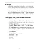
Page 4: ...s and BIOS setup of the EXPC 1319 For software configuration and management please refer to the user s manual for your operating system The following topics are covered in this chapter Overview Model...

Page 5: ...g them scratch and glare resistant and easy to read even during the peak daylight hours Model Descriptions and Package Checklist The EXPC 1319 Series includes the following models EXPC 1319 STS W7E Fa...

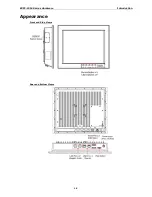
Page 6: ...EXPC 1319 Series Hardware Introduction 1 3 Appearance Front and Side Views Rear and Bottom Views...

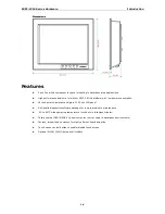
Page 7: ...resistant anti glare 1000 nits LCD panel Self health diagnostics software package for remote predictive maintenance 40 to 60 C wide operating temperature with built in Intelligent Heater Totally seal...

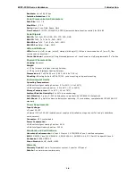
Page 8: ...ade SSD operating temperature 40 to 85 C to store OS supports up to 256 GB Display Panel Size 19 inch SXGA 1000 nits LED backlit LCD Aspect Ratio 5 4 Response Time 5 ms Contrast Ratio 1000 1 Viewing A...

Page 9: ...unting Environmental Limits Operating Temperature Without Intelligent Heating Solution 20 to 60 C 4 to 140 F With Intelligent Heating Solution 40 to 60 C 40 to 140 F Storage Temperature 40 to 80 C 40...

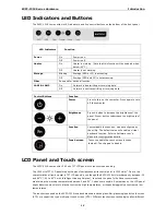
Page 10: ...ility The default value will enable a virtual keyboard function Refer to Software User s Manual for configuration details Touch screen Touch to enable the touch screen function default Touch again to...

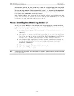
Page 11: ...be ordered with Moxa s patented Intelligent Heating Solution to extend the effective range of the platform s operating temperature with the caveats below EXPC 1319 computers equipped with IHS feature...

Page 12: ...easy to maintain allowing you to spend your time on application development rather than troubleshooting networking bugs This chapter describes the hardware installation and interfaces of EXPC 1319 pa...

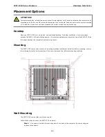
Page 13: ...refer to the following figure for the dimensions of the screw holes used for different mounting methods Wall Mounting The EXPC 1319 comes with a wall mounting kit Follow these steps to mount the EXPC...

Page 14: ...e When choosing screws for installation remember to account for the thickness of the mounting surface Other Mounting Solutions The EXPC 1319 computers have reserved various mounting holes for users to...

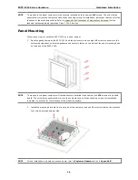
Page 15: ...en the EXPC 1319 and the enclosure and use eight M6 screws to penetrate the enclosure and gasket so that the gasket can be securely fasten on two sides of the panel mounting holes on the back of the E...

Page 16: ...s 1 Div 2 devices Wiring Requirements The following common safety precautions should be observed before installing any electronic device Strive to use separate non intersecting paths to route power an...

Page 17: ...too hot to touch Connecting the Power Supply The power connector is located at the far left of the bottom panel When wiring the machine for power refer to the following figure for the pinout of the M1...

Page 18: ...etails regarding regulation Class 1 Div 2 devices DB 15 Female VGA Connector Pin No Signal Definition Pin No Signal Definition 1 Red 9 VCC 2 Green 10 GND 3 Blue 11 NC 4 NC 12 DDC2B Data 5 GND 13 HSYNC...

Page 19: ...s users should disconnect the entire computer from its power source before connecting or disconnecting any USB devices You may refer to Appendix B Statement of Regulatory Approval for the technical de...

Page 20: ...of RJ45 connectors Follow the steps below to connect the LAN ports By default the LAN ports use DHCP addressing to assign network IP addresses For detailed network configuration please refer to the EX...

Page 21: ...have been securely fastened to keep water from entering the enclosure Please note that when reinstalling the protective caps they must be tightened to 136 N cm 12 in lbs to ensure the unit is sealed t...

Page 22: ...at left 5 Set the SSD cover in place and fasten it using the original four screws NOTE Please note that the operating system is stored on the SSD If you replace this SSD with a new model you will may...

Page 23: ...r or other long slender tool 4 When finished place the cover back and fasten the screws NOTE Please note that the SSD CompactFlash cover comes with rubber pads fastened to the back plate to help secur...

Page 24: ...ouch Screen Calibration Calibrating the Touch Screen Standard Calibration Advanced Calibration PenMount Calibration Utility Parameters Turn off EEPROM Storage Touch Screen Cursor Settings Edge Compens...

Page 25: ...EXPC 1319 Series Hardware Hardware Installation 2 2...

Page 26: ...t the standard calibration is not adequate for re establishing screen accuracy and precision If problems are still encountered following a standard calibration you may choose Advanced Calibration to c...

Page 27: ...enMount calibration utility please contact Moxa s Embedded Computing Technical Support staff PenMount Calibration Utility Parameters Turn off EEPROM Storage Ticking this box disables the storage of ca...

Page 28: ...e in most Windows applications Back to defaults resets all of the touch screen interface settings to their factory defaults When finished click OK Edge Compensation This page allows users to calibrate...

Page 29: ...the user to modify the system configurations of these basic input output peripherals All of the configurations will be stored in the NVRAM flash memory which retains the system information after syste...

Page 30: ...he BIOS setup utility press the F2 key while the system is booting up The main BIOS Setup screen will appear A basic description of each function key is listed at the bottom of the screen Refer to the...

Page 31: ...menu while left and right arrows will open or close sub menus from entries marked with a triangle at the beginning of the line Advanced Settings The Advanced Features screen will appear when choosing...

Page 32: ...default Disabled Serial Port B This item allows you to configure the COM2 port Options 2F8 IRQ3 default Disabled Serial Port C This item allows you to configure the control buttons Options 3E8 IRQ5 d...

Page 33: ...d Channel Master 1 to 3 This setting displays the storage devices installed on the computer s master bus These storage devices may be HDD SSD or a CF card Channel Slave 1 to 3 This setting displays st...

Page 34: ...ect the video device which will be activated during POST Options CRT LCD default CRT LCD Please note that for the EXPC 1319 the LCD features the LCD panel and the CRT features the VGA port at the bott...

Page 35: ...USB Port1 This item allows you to configure the USB Port 2 Options Enabled default Disabled USB Port3 Port6 This item allows you to configure the USB Port 3 to 6 These ports are reserved on the main b...

Page 36: ...enable disable the HPET High Precision Event Timer which produces periodic interrupts at a much higher resolution than the RTC and may be used to synchronize multimedia streams HPET can sometimes intr...

Page 37: ...s The section allows users to configure security settings like a system supervisor password and user password Set Supervisor Password This item allows you to set the supervisor password Select and the...

Page 38: ...word If you wish to simply cancel the password and leave the system unprotected you may leave the password update box blank WARNING To guarantee your hard drive remains accessible remember to record y...

Page 39: ...ion and response time However in some instances users may want to disable it to conserve power or reduce CPU cache paging Options Enable default Disabled Use XD Capability This item allows you to enab...

Page 40: ...t Disable Auto Wake on S5 This item allows you to configure the computer to wake from S5 status S5 stands for Soft Off where the PSU remains engaged but power to all other parts of the system is cut A...

Page 41: ...s item displays the boot selection for the UEFI boot function Legacy Normal Boot Menu This item allows you to configure the boot menu Options Normal default Advanced Boot Type Order This item allows y...

Page 42: ...default No Exit Discarding Changes This item allows you to exit the BIOS without saving any new settings from the user session Options Yes default No Load Defaults Setting This item resets the entire...

Page 43: ...ce A useful software suite for building USB RAM drives may be found by searching for HP USB Disk Storage Format Tool which may then be downloaded and used to create a bootable RAM drive To create a re...

Page 44: ...quest to Moxa s technical support team at support moxa com to get an updated version of the BIOS 1 Get the BIOS upgrade installation file The file name should have following format 139xxSyy exe xx and...

Page 45: ...hat the upgrade filename may vary depending on the firmware version C EXPC1319 13911S01 exe 5 The upgrade program will run Wait until the procedure is finished before initiating any changes to the sys...

Page 46: ...EXPC 1319 Series Hardware BIOS Setup 3 18 ATTENTION Do NOT switch off the power supply during the BIOS upgrade Doing so will likely cause permanent damage to your system...

Page 47: ...flow required for safe operation is not obstructed 3 Mechanical Loading Mounting of the equipment in the rack should not create hazards that result from uneven mechanical loading 4 Circuit Overloading...

Page 48: ...19 Series Hardware Safety Installation Instructions A 2 2 External metal parts can get dangerously hot Before touching it give special attention to device temperature Protective wear will likely be ne...

Page 49: ...ntial area is likely to cause harmful interference in which case the user will be required to correct the interference at his own expense European Community Warning This is a Class A product In a dome...

Page 50: ...Division 2 ATEX Zone 2 EN 60079 15 and IECEx Do not connect or disconnect equipment unless power has been switched off or the area is known to be non hazardous Do not install or remove CompactFlash ca...

Reviews: