EXPC-1319 Series Hardware
Hardware Installation
2-5
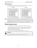
VESA Mounting
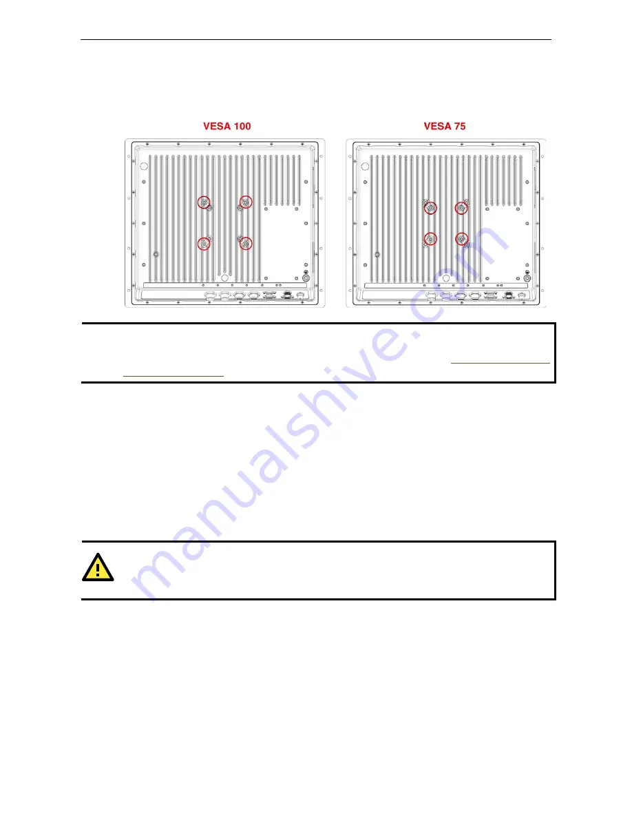
The EXPC-1319 comes with two sets of holes reserved for VESA mounts (FDMI): VESA 100 and VESA 75. Refer
to the following figures for the specific locations of the VESA mounting screw holes.
NOTE
To make sure the panel computer will be securely installed on a wall, we suggest you to use the screws with the
specifications of M4. The screw holes penetrate 6 mm into the computer’s case. When choosing screws for
installation, remember to account for the thickness of the mounting surface. Refer to
Appendix B: Statement
of Regulatory Approval
for the technical details regarding regulation Class 1 Div. 2 devices.
Wiring Requirements
The following common safety precautions should be observed before installing any electronic device:
•
Strive to use separate, non-intersecting paths to route power and networking wires. If power wiring and
device wiring paths must cross, make sure the wires are perpendicular at the intersection point.
•
Keep the wires separated according to interface. The rule of thumb is that wiring that shares similar
electrical characteristics may be bundled together.
•
Do not bundle input wiring with output wiring. Keep them separate.
•
When necessary, it is strongly advised that you label wiring to all devices in the system.
ATTENTION
Do not run signal or communication wiring and power wiring in the same conduit. To avoid interference, wires
with different signal characteristics (i.e., different interfaces) should be routed separately.

