- 4 -
AC Power Inlets
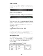
The connection for PWR1 (power supply 1) and PWR2 (power supply 2)
are located on the rear side (shown below). Be sure to use a standard
power cord with an IEC C13 connector, which is compatible with the AC
power inlet.
DC Power Terminal Blocks
The connection for PWR1 (power supply 1) and PWR2 (power supply 2)
are located on the rear side (shown below).
STEP 1: Insert the negative/positive DC wires into the V-/V+ terminals,
respectively.
STEP 2: To keep the DC wires from pulling loose, use a small flat-blade
screwdriver to tighten the wire-clamp screws on the front of the terminal
block connector.
STEP 3: Insert the plastic terminal block connector prongs into the
terminal block receptor.
Wiring the Relay Contact
Each IKS-6726/6728 switch has one relay output.
FAULT:
The relay contact of the 2-pin terminal block connector is used to detect
user-configured events. The two wires attached to the fault contacts form
an open circuit when a user-configured event is triggered. If a
user-configured event does not occur, the fault circuit remains closed.
RS-232 Connection
The Moxa IKS-6726/6728 has one RS-232 (10-pin RJ45) console port,
located on the front panel. Use either an RJ45-to-DB9 or RJ45-to-DB25
cable to connect Moxa IKS-6726/6728 console port to your PC’s COM port.
You may then use a console terminal program, such as Moxa PComm
Terminal Emulator, to access Moxa IKS-6726/6728’s console
configuration utility.
RJ45 (10-pin) Console Port Pinouts
Pin Description Pin Description
1
–
6
RxD
2
DSR
7
GND
3
–
8
–
4
GND
9
DTR
5
TxD
10 –


