background image


 2014 Moxa Inc. All rights reserved. 


P/N: 1802005102012 

PT-510 Series 

Hardware Installation Guide 

Moxa PowerTrans Switch 

Fourth Edition, January 2014 


Summary of Contents for PT-510 Series

Page 1: ... 2014 Moxa Inc All rights reserved P N 1802005102012 PT 510 Series Hardware Installation Guide Moxa PowerTrans Switch Fourth Edition January 2014 ...

Page 2: ... is missing or damaged please contact your customer service representative for assistance PT 510 PowerTrans switch RJ45 to DB9 console port cable DIN Rail Kit or wall mount plates optional 1 grounding cable Protective caps for unused ports Documentation and software CD Hardware installation guide Warranty card ...

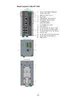
Page 3: ...R HEAD LED indicator 5 CPLR TAIL LED indicator 6 100BaseFX ports SC ST LC MTRJ 7 10 100BaseT X ports 8 Model Name 9 Terminal block for power input 10 Screw hole for grounding cable 11 Terminal block for DI and Relay 1 12 Console port 13 Screw hole for wall mounting kit 14 Screw hole for DIN Rail kit 15 DIN Rail kit ...

Page 4: ... 4 Mounting Dimensions unit mm ...

Page 5: ...o release it Once released you should feel some resistance from the spring as you slide the bracket up and down a few millimeters in each direction STEP 2 Insert the top of the DIN Rail into the top slots on the DIN Rail attachment plate STEP 3 The DIN Rail attachment unit will snap into place as shown in the following illustration To remove the Moxa PT 510 switch from the DIN Rail use a screwdriv...

Page 6: ... keyhole shaped apertures of the wall mounting plates before screwing it into the wall DO NOT screw the screws all the way in leave a space of about 2 mm to allow room for sliding the wall mount panel between the wall and the screws STEP 3 After the screws are fixed into the wall insert the four screw heads through the large opening of the keyhole shaped apertures and then slide the PT 510 downwar...

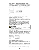
Page 7: ...y advised that you label wiring to all devices in the system Grounding the PowerTrans Switch Grounding and wire routing help limit the effects of noise due to electromagnetic interference EMI Run the ground wire from the grounding screw to the grounding surface prior to connecting devices ATTENTION Before powering on the PT 510 24 48 VDC models make sure that the grounding cable is secured between...

Page 8: ...ed Wiring the Redundant Power Inputs 24 48 VDC models The PT 510 24 48 VDC models unit has two sets of power inputs power input 1 and power input 2 Top and front views of one of the terminal block connectors are shown below Take the following steps to wire the redundant power inputs STEP 1 Insert the negative positive DC wires into the V V terminals and insert the AC power wires into the L and N t...

Page 9: ...connector prongs into the terminal block receptor which is located on the PT s bottom panel NOTE The PT 510 unit 110 220 VDC VAC model has the reverse protection mechanism for 110 220 VDC input ATTENTION Before connecting the PT to the DC power inputs make sure the DC power source voltage is stable Wiring the Digital Inputs The PT 510 unit has one set of digital input DI 1 The DI consists of two c...

Page 10: ...The 10 100BaseT X ports located on PT s front panel are used to connect to Ethernet enabled devices Next we show pinouts for both MDI NIC type ports and MDI X HUB Switch type ports and also show cable wiring diagrams for straight through and cross over Ethernet cables RJ45 8 pin to RJ45 8 pin Straight Through Cable Wiring RJ45 8 pin to RJ45 8 pin Cross Over Cable Wiring ...

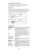
Page 11: ...transmit port of device 2 If you make your own cable we suggest labeling the two sides of the same line with the same letter A to A and B to B as shown below or A1 to A2 and B1 to B2 SC Port Pinouts SC Port to SC Port Cable Wiring ST Port Pinouts ST Port to ST Port Cable Wiring ATTENTION This is a Class 1 Laser LED product To avoid causing serious damage to your eyes do not stare directly into the...

Page 12: ...ster of this Turbo Ring and the Turbo Ring is broken or 3 Start up fails Off When a relay warning event is not triggered MSTR HEAD GREEN On When the PT switch is set as the Master of the Turbo Ring or as the Head of the Turbo Chain Blinking The PT switch has become the Ring Master of the Turbo Ring or the Head of the Turbo Chain after the Turbo Ring or the Turbo Chain is down Off The PT switch has...

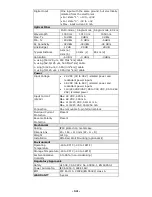
Page 13: ...2 3u 802 3x 802 1D 802 1w 802 1Q 802 1p 802 1X 802 3ad Protocols IGMPv1 v2 GVRP SNMPv1 v2c v3 DHCP Server Client BootP TFTP SNTP SMTP RARP GMRP LACP RMON HTTP HTTPS Telnet Syslog DHCP Option 66 67 82 SSH SNMP Inform Modbus TCP LLDP IEEE 1588 PTP IPv6 MIB MIB II Ethernet Like MIB P BRIDGE MIB Q BRIDGE MIB Bridge MIB RSTP MIB RMON MIB Group 1 2 3 9 Forwarding and Filtering Rate 148810 pps Processing...

Page 14: ...lated power and redundant power inputs 48 VDC 36 to 60 V isolated power and redundant power inputs 110 220 VDC VAC 88 to 300 VDC 85 to 264 VAC isolated power Input Current 24V Max 24 VDC 425 mA Max 48 VDC 190 mA Max 110 220 VDC 56 111 mA Max 110 220 VAC 160 254 mA Connection One removable 5 pin terminal block Overload Current Protection Present Reverse Polarity Protection Present Mechanical Casing...

Page 15: ...icas Toll free 1 888 669 2872 Tel 1 714 528 6777 Fax 1 714 528 6778 Moxa China Shanghai office Toll free 800 820 5036 Tel 86 21 5258 9955 Fax 86 21 5258 5505 Moxa Europe Tel 49 89 3 70 03 99 0 Fax 49 89 3 70 03 99 99 Moxa Asia Pacific Tel 886 2 8919 1230 Fax 886 2 8919 1231 ...

Reviews: