background image


- 2 -

Package Checklist 

The Moxa PowerTrans switch is shipped with the following items. If any of 
these items are missing or damaged, please contact your customer service 
representative for assistance. 

y


1 Moxa PowerTrans Switch 

y


Hardware Installation Guide 

y


CD-ROM with User’s Manual and SNMP MIB file 

y


Moxa Product Warranty Statement 

y


RJ45 to DB9 console port cable 

y


Protective caps for unused ports 

y


2 rack-mount ears 


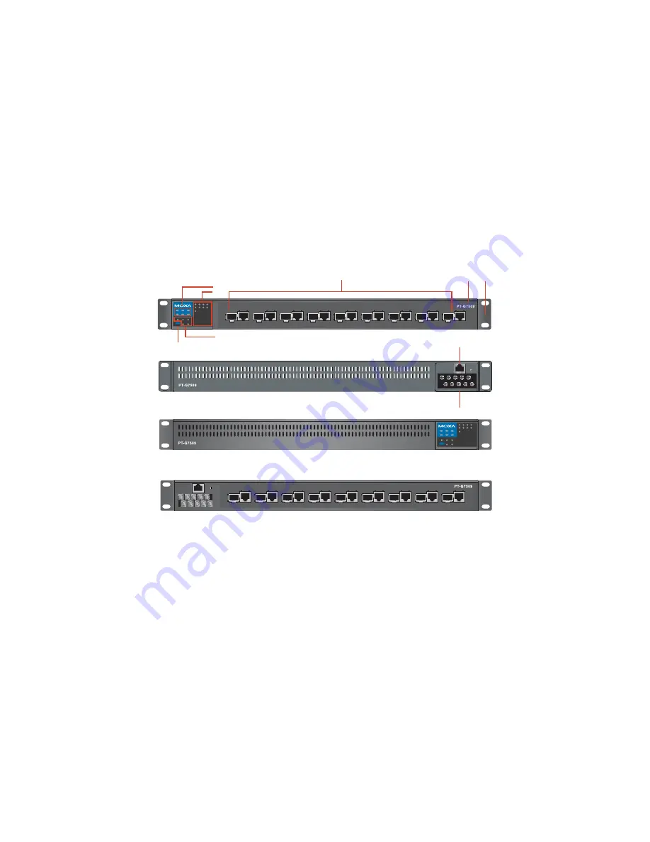
Panel Layout 

Front view (Front Cabling)

Front view (Rear Cabling)

Rear view (Front Cabling)

Rear view (Rear Cabling)

8

7

6

9

STAT

FAULT

PWR1

MASTER

PWR2

COUPLER

LNK/ACT

SPEED

FDX/HDX

RING PORT

COMUPLER 

PORT

MODE

CONSOLE

STAT

FAULT

PWR1

MASTER

PWR2

COUPLER

LNK/ACT

SPEED

FDX/HDX

RING PORT

COMUPLER 

PORT

MODE

1

2

3

4

5

6

7

8

9

1

2

3

4

5

6

7

8

9

4

2

3

1

5


1. 

System status LEDs 

2. 

Interface Module mode LEDs 

3. 

9 Gigabit Combo port LEDs 

4. 

Push-button switch to select mode for Interface Module 

5. Model 

Name 

6. 

9 Gigabit Combo ports 

7. 

Serial Console port 

8. 

10-pin terminal block for power inputs, and relay output 

9. 

Rack Mounting Kit   

Summary of Contents for PT-G7509

Page 1: ...Hardware Installation Guide Fourth Edition June 2010 2010 Moxa Inc All rights reserved Reproduction without permission is prohibited Fl 4 No 135 Lane 235 Pao Chiao Rd Shing Tien City Taipei Taiwan R O C TEL 886 2 8919 1230 P N 1802075090013 ...

Page 2: ...rs Panel Layout Front view Front Cabling Front view Rear Cabling Rear view Front Cabling Rear view Rear Cabling 8 7 6 9 STAT FAULT PWR1 MASTER PWR2 COUPLER LNK ACT SPEED FDX HDX RING PORT COMUPLER PORT MODE CONSOLE STAT FAULT PWR1 MASTER PWR2 COUPLER LNK ACT SPEED FDX HDX RING PORT COMUPLER PORT MODE 1 2 3 4 5 6 7 8 9 1 2 3 4 5 6 7 8 9 4 2 3 1 5 1 System status LEDs 2 Interface Module mode LEDs 3 ...

Page 3: ...fore installing and or wiring your Moxa PowerTrans Switch Calculate the maximum possible current in each power wire and common wire Observe all electrical codes dictating the maximum current allowable for each wire size If the current goes above the maximum ratings the wiring could overheat causing serious damage to your equipment Grounding Moxa PowerTrans Switch Grounding and wire routing help li...

Page 4: ...ached to the RELAY contacts form an open circuit when a user configured event is triggered If a user configured event does not occur the RELAY circuit will be closed Wiring the Redundant Power Inputs Each PT switch has two sets of power inputs power input 1 and power input 2 STEP 1 Insert the dual set positive negative DC wires into PWR1 and PWR2 terminals pins 1 9 pins 2 10 Or insert the L N AC w...

Page 5: ...The corresponding PORT alarm is enabled and a user configured event has been triggered Off The corresponding PORT alarm is enabled and a user configured event has not been triggered or the corresponding PORT alarm is disabled MSTR HEAD GREEN On This PT switch is set as the Master of the Turbo Ring or as the Head of the Turbo Chain Blinking This PT switch has become the Ring Master of the Turbo Rin...

Page 6: ...g module s port is the coupler port of this PT switch Off The corresponding module s port is not the coupler port of this PT switch Specifications Technology Standards IEEE 802 3 802 3u 802 3ab 802 3z 802 3x 802 1D 802 1W 802 1Q 802 1p 802 1X 802 3ad Flow control IEEE 802 3x flow control back pressure flow control Interface Fiber Ports 100 1000BaseSFP slot RJ45 Ports 10 100 1000BaseT X auto negoti...

Page 7: ... min 100 VAC at 40 C Storage Temp 40 to 85 C 40 to 185 F Ambient Relative Humidity 5 to 95 non condensing Warranty 5 years Technical Support Contact Information www moxa com support Moxa Americas Toll free 1 888 669 2872 Tel 1 714 528 6777 Fax 1 714 528 6778 Moxa China Shanghai office Toll free 800 820 5036 Tel 86 21 5258 9955 Fax 86 10 5258 5505 Moxa Europe Tel 49 89 3 70 03 99 0 Fax 49 89 3 70 0...

Reviews: