background image


P/N: 1802049080010 

*1802049080010* 

TN-4900 Series   

Quick Installation Guide 

Moxa ToughNet Router 

Version 1.0, March 2021 

Technical Support Contact Information 

www.moxa.com/support 


 2021 Moxa Inc. All rights reserved. 


Summary of Contents for TN-4900 Series

Page 1: ...1802049080010 1802049080010 TN 4900 Series Quick Installation Guide Moxa ToughNet Router Version 1 0 March 2021 Technical Support Contact Information www moxa com support 2021 Moxa Inc All rights rese...

Page 2: ...our customer service representative for assistance TN 4900 router Protective caps for the console port x1 Ethernet ports TN 4908 x4 TN 4916 x8 and USB storage port x1 Panel mounting kit Quick installa...

Page 3: ...e Panel mounting installation capability This product is suitable for rolling stock railway applications as defined by the EN 50155 standard For a more detailed statement click here www moxa com doc s...

Page 4: ...6 PWR2 LED for power input 2 7 10 100 1000BaseT X port M12 X coded 8 pin female connector 8 10 100 1000BaseT X port LED 9 PoE LED 10 Grounding screw 11 Power input port M12 K coded 5 pin male connecto...

Page 5: ...connector 8 10 100 1000BaseT X port LED 9 PoE LED 10 Grounding screw 11 Power input port M12 K coded 5 pin male connector 12 CPLR TAIL LED for ring coupler or chain tail 13 MSTR HEAD LED for ring mas...

Page 6: ...6 Mounting Dimensions unit mm TN 4908 PoE Models...

Page 7: ...7 TN 4908 Non PoE Models...

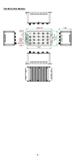
Page 8: ...8 TN 4916 PoE Models...

Page 9: ...he keyhole shaped apertures of the ToughNet router STEP 3 Once the screws are fixed in the wall hang the ToughNet router on the 4 screws through the large opening of the keyhole shaped apertures and t...

Page 10: ...make sure the wires are perpendicular at the intersection point NOTE Do not run signal or communications wiring and power wiring through the same wire conduit To avoid interference wires with differen...

Page 11: ...nal when using a DC power source 2 PWR1 DC Connect PWR1 Neutral DC to the negative terminal when using a DC power source 3 PWR2 DC Connect PWR2 Neutral DC to the negative terminal when using a DC powe...

Page 12: ...ase the port s pinouts are adjusted automatically depending on the type of Ethernet cable used straight through or cross over and the type of device NIC type or HUB Switch Router type connected to the...

Page 13: ...t to Ethernet enabled devices Most users configure these ports for Auto MDI MDI X mode in which case the port s pinouts are adjusted automatically depending on the type of Ethernet cable used straight...

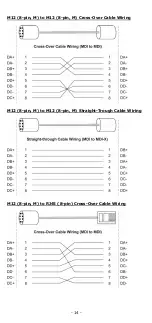
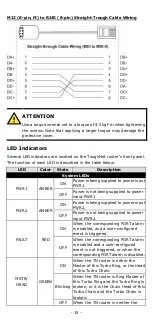
Page 14: ...14 M12 8 pin M to M12 8 pin M Cross Over Cable Wiring M12 8 pin M to M12 8 pin M Straight Trough Cable Wiring M12 8 pin M to RJ45 8 pin Cross Over Cable Wiring...

Page 15: ...to power input PWR1 PWR2 AMBER ON Power is being supplied to power input PWR2 OFF Power is not being supplied to power input PWR2 FAULT RED ON When the corresponding PORT alarm is enabled and a user...

Page 16: ...n FAULT MSTR HEAD CPLR TAIL Rotate Blinking Sequentially When ABC 02 is importing or exporting files LED Color State Description Port LEDs TP Ports 10 100 1000M for copper ports AMBER On TP port s 10...

Reviews: