- 14 -
NOTE
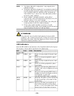
1.
“Hardware-based IP configuration” only supports IPv4
address settings.
2.
“Hardware-based IP configuration” is enabled only when the
3 rotary switches are set to values ranging from 001 to 254.
The ToughNet switch’s IP address will be configured as
“192.168.127.xxx”, where “xxx” are valid value numbers
set by the rotary switches.
3.
When enabled, “Hardware-based IP configuration”
overrides the “Auto IP Configuration” described in the “IP
Settings” section in the user’s manual.
4.
Disable “Hardware-based IP configuration” by setting the 3
rotary switches to 000 (the factory default).
5.
If the rotary switch numbers are set to an invalid
combination (255 to 999), the ToughNet switch will use the
fixed IP address 192.168.127.253 by default.
ATTENTION
The protective cover must be fixed properly to ensure IP54
protection. Use a torque wrench set to a torque of 4 kgf-m when
tightening the screws. Note that applying a larger torque may
damage the plastic protective cover.
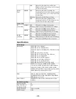
LED Indicators
Several LED indicators are located on the ToughNet switch’s front panel.
The function of each LED is described in the table below.
LED
Color
State Description
System LEDs
PWR1
AMBER ON
Power is being supplied to power input
PWR1.
OFF
Power is not being supplied to power
input PWR1
PWR2
AMBER ON
Power is being supplied to power input
PWR2.
OFF
Power is not being supplied to power
input PWR2.
FAULT
RED
ON
When the corresponding PORT alarm is
enabled, and a user-configured event is
triggered.
OFF
When the corresponding PORT alarm is
enabled and a user-configured event is
not triggered, or when the
corresponding PORT alarm is disabled.
MSTR/
HEAD
GREEN ON
When the TN switch is either the Master
of this Turbo Ring, or the Head of this
Turbo Chain.
Blinking When the TN switch is Ring Master of
this Turbo Ring and the Turbo Ring is
broken, or it is Chain Head of this Turbo
Chain and the Turbo Chain is broken.


