background image

- 11 - 

2.


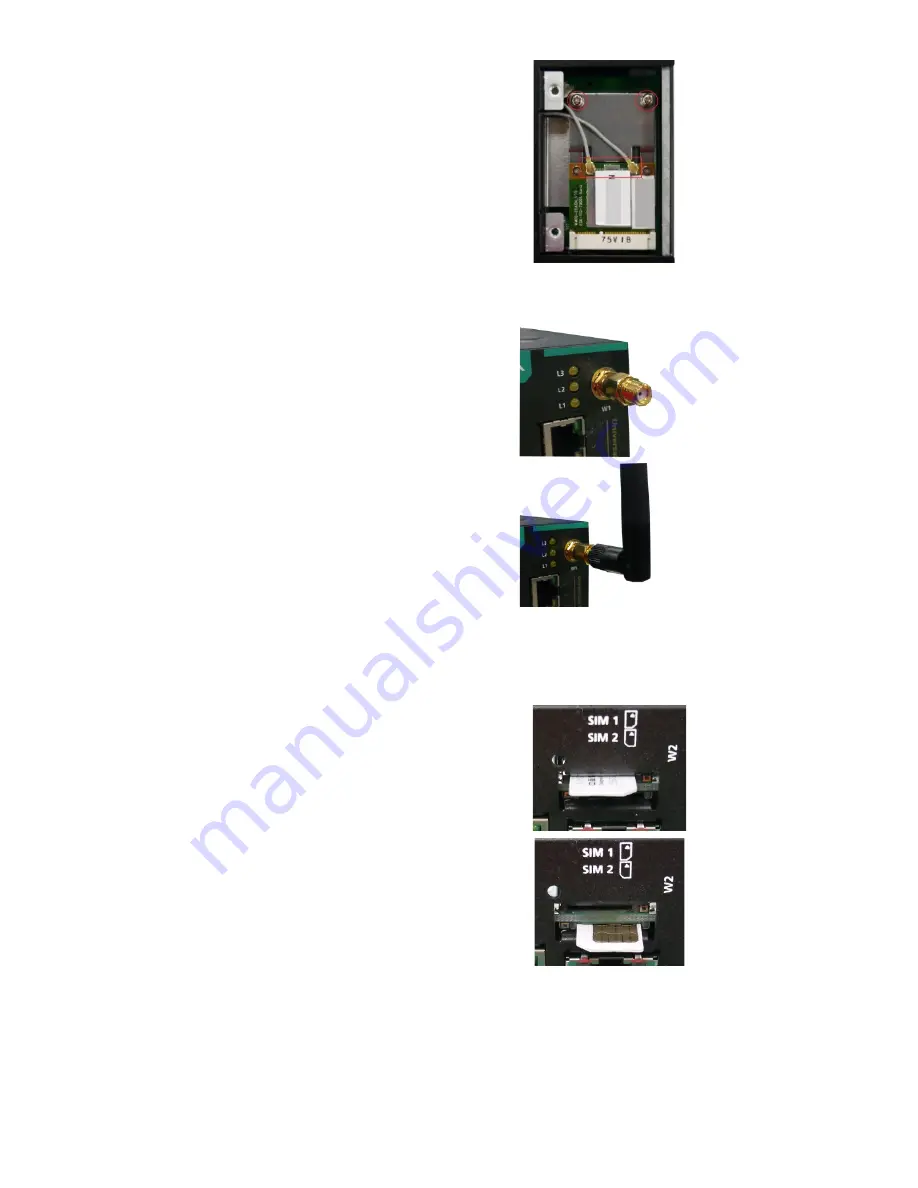
Insert the cellular module 
into the socket and fasten 
two screws (included in the 
package) on to the top of the 
module. 
We recommended using a 
tweezer when installing or 
removing the module. 

3.


Connect the free ends of the 
two antenna cables next to 
the screws as shown in the 
image. 

4.


Replace the cover and secure 
it with two screws. 


5.


Connect the antenna 
adapters to the connectors on 
the front panel of the 
computer. 


6.


Connect the Wi-Fi antennas 
to the antenna adapters. 


Installing Micro SIM Cards 

You will need to install a Micro SIM card on your UC-5100 computer. 
Follow these steps to install the Micro SIM card. 

1.


Remove the screw on the cover 
located on the front panel of the 
UC-5100. 


2.


Insert the Micro SIM card into the 
socket. Make sure you place the 
card in the right direction. 
 

To remove the Micro SIM card, 
simply push the Micro SIM card and 
release it. 
Note: There are two Micro SIM card 
sockets allowing users to install two 
Micro SIM cards simultaneously. 
However, only one Micro SIM card 
can be enabled for use. 


Summary of Contents for UC-5100 Series

Page 1: ...ericas Toll free 1 888 669 2872 Tel 1 714 528 6777 Fax 1 714 528 6778 Moxa China Shanghai office Toll free 800 820 5036 Tel 86 21 5258 9955 Fax 86 21 5258 5505 Moxa Europe Tel 49 89 3 70 03 99 0 Fax 49 89 3 70 03 99 99 Moxa Asia Pacific Tel 886 2 8919 1230 Fax 886 2 8919 1231 Moxa India Tel 91 80 4172 9088 Fax 91 80 4132 1045 2018 Moxa Inc All rights reserved ...

Page 2: ...computing platform with 4 serial ports 2 Ethernet ports SD socket mini PCIe socket 2 CAN ports 4 DI 4 DO 10 to 60 C operating temperature range UC 5101 T LX Industrial computing platform with 4 serial ports 2 Ethernet ports SD socket 4 DI 4 DO 40 to 85 C operating temperature range UC 5102 T LX Industrial computing platform with 4 serial ports 2 Ethernet ports SD socket mini PCIe socket 4 DI 4 DO ...

Page 3: ... 3 NOTE The console cable and power jack can be found beneath the molded pulp cushioning inside the product box Appearance UC 5101 UC 5102 ...

Page 4: ...ice is functioning normally Off Power is off Ready Yellow OS has been successfully enabled and the device is ready Ethernet Green Steady On 10 Mbps Ethernet link Blinking Data transmission is in progress Yellow Steady On 100 Mbps Ethernet link Blinking Data transmission is in progress Off Transmission speed below 10 Mbps or the cable is not connected ...

Page 5: ...an be used to reset the operating system back to the factory default status Press and hold the Reset to Default button between 7 to 9 seconds to reset the computer to the factory default settings When the reset button is held down the Ready LED will blink once every second The Ready LED will become steady when you hold the button continuously for 7 to 9 seconds Release the button within this perio...

Page 6: ...ible current in each power wire and common wire Observe all electrical codes dictating the maximum current allowable for each wire size If the current goes above the maximum ratings the wiring could overheat causing serious damage to your equipment This equipment is intended to be supplied by a certified External Power Supply the output of which meets SELV and LPS regulations Temperature Caution B...

Page 7: ...viewing boot up messages or for debugging system boot up issues PIN Signal 1 2 3 GND 4 TxD 5 RxD 6 7 8 Connecting to the Network The Ethernet ports are located on the front panel of the UC 5100 The pin assignments for the Ethernet port are shown in the following figure If you are using your own cable make sure that the pin assignments on the Ethernet cable connector match the pin assignments on th...

Page 8: ...uts The DI DO connectors are located on the top panel of the computer Refer to the adjacent diagram for the pin definitions The DI DO wiring diagram is given below Connecting to a CAN Device The UC 5111 and UC 5112 are provided with 2 CAN ports allowing users to connect to a CAN device The pin location and assignments are shown in the following table PIN Signal 1 CAN_H 2 CAN_L 3 CAN_GND 4 5 6 7 CA...

Page 9: ...t panel to remove the cover and find the location of the socket The cellular module package includes 1 cellular module and 2 screws The cellular antennas should be purchased separately to fit your installation requirements Follow these steps to install the cellular module 1 Set the antenna cables aside for convenience of installation and clear the wireless module socket as shown in the figure ...

Page 10: ...the cover and secure it using two screws 5 Connect the cellular antennas to the connectors Antenna connectors are located on the front panel of the computer The Wi Fi module package includes 1 Wi Fi module and 2 screws The antenna adapters and Wi Fi antennas should be purchased separately to fit your installation requirements Follow these steps to install a Wi Fi module 1 Set the antenna cables as...

Page 11: ...e computer 6 Connect the Wi Fi antennas to the antenna adapters Installing Micro SIM Cards You will need to install a Micro SIM card on your UC 5100 computer Follow these steps to install the Micro SIM card 1 Remove the screw on the cover located on the front panel of the UC 5100 2 Insert the Micro SIM card into the socket Make sure you place the card in the right direction To remove the Micro SIM...

Page 12: ...omputers come with one CAN DIP switch for users to adjust the CAN termination resistor parameters To set up the DIP switch do the following 1 Find the DIP switch location on the top panel of the computer 2 Adjust the setting as required The ON value is 120Ω and the default value is OFF Adjusting the Serial Port DIP Switch The UC 5100 computers come with a DIP switch for users to adjust the pull up...

Reviews: