- 8 -
Pin
RS-232
RS-422 RS-485
1
DSR
-
-
2
RTS
TxD+
-
3
GND
GND
GND
4
TxD
TxD-
-
5
RxD
RxD+
Data+
6
DCD
RxD-
Data-
7
CTS
-
-
8
DTR
-
-
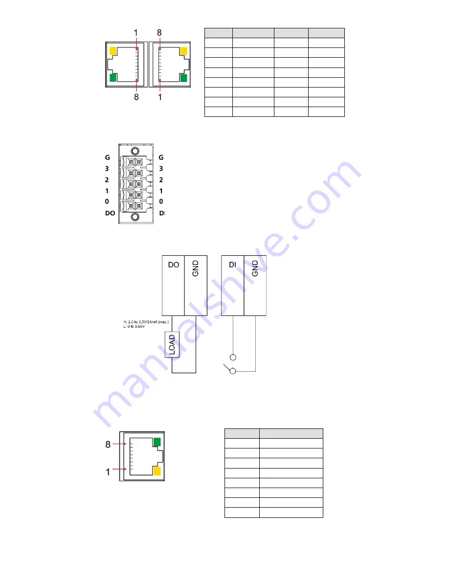
Connecting to DI/DO Devices
The UC-5100 computer comes with
4 digital inputs and 4 digital
outputs. The DI/DO connectors are
located on the top panel of the
computer. Refer to the adjacent
diagram for the pin definitions.
The DI/DO wiring diagram is given below:
Connecting to a CAN Device
The UC-5111 and UC-5112 are provided with 2 CAN ports, allowing
users to connect to a CAN device. The pin location and assignments are
shown in the following table:
PIN
Signal
1
CAN_H
2
CAN_L
3
CAN_GND
4
-
5
-
6
-
7
CAN_GND
8
-


