

— 4 —
— 5 —
— 6 —
PS/2 Connector
The V481 has a PS/2 connector for connecting a PS/2 keyboard or PS/2
mouse. This 6-pin mini-DIN connector has the following pin
assignments.
PS/2 Connector Pin No.
Signal Definition
1
PS/2 keyboard signal
2 PS/2
mouse
clock
3 GND
4 VCC
5
PS/2 keyboard clock
1
2
4
6
5
3
6 PS/2
mouse
data
And please be informed that for product version 1.1 and later new pin
assignment has changed as below:
PS/2 Connector Pin No.
Signal Definition
1
PS/2 keyboard signal
2 PS/2
mouse
data
3 GND
4 VCC
5
PS/2 keyboard clock
1
2
4
6
5
3
6 PS/2
mouse
clock
A Y-type cable is included as a standard accessory for connecting a PS/2
keyboard and PS/2 mouse at the same time.
Ethernet Ports
Both the 10/100 and 10/100/1000 Mbps Ethernet ports use RJ45
connectors.
Pin Signal
1 ETx+
2 ETx-
3 ERx+
6 ERx-
1
8
Serial Ports
The serial ports use DB9 connectors. Each port can be configured by
software for RS-232, RS-422, or RS-485. The pin assignments for the
ports are shown in the following table:
Pin
RS-232
RS-422
RS-485
(4-wire)
RS-485
(2-wire)
1 DCD TxDA(-)
TxDA(-)
---
2 RxD TxDB(+)
TxDB(+)
---
3 TxD RxDB(+)
RxDB(+)
DataB(+)
4 DTR RxDA(-)
RxDA(-)
DataA(-)
5 GND GND GND GND
6 DSR
---
---
---
7 RTS
---
---
---
8 CTS
---
---
---
1 2 3 4 5
6 7 8 9
SO-DIMM Socket for Memory Module
The V481 has an internal 200-pin SO-DIMM socket for installing a DDR
SDRAM memory module. The V481-XPE comes with a 512 MB DDR
SDRAM Module pre-installed. You may also replace the module with
your own (128 MB to 1 GB) DDR SDRAM memory module. To replace
the module, first remove the bottom cover of the V481 to expose the
SO-DIMM socket.
Compact Flash Socket
The V481-XPE comes with a built-in 1 GB industrial CompactFlash card
to store the WinXP Embedded operating system. A second CompactFlash
socket is located inside the V481. Installing a second CompactFlash
memory card will not affect the operating system. Remove the bottom
cover of the V481 to install the second CompactFlash card.
USB Hosts
The V481 supports two USB 2.0 hosts. Both hosts are UHCI, Rev. 2.0
compliant and support Plug & Play and also hot swapping. Both hosts can
be used to connect any USB device, such as a keyboard, mouse, USB
flash disk, or USB CD-ROM. In addition, both USB ports support system
boot up, which is activated by changing BIOS settings.
Audio Interface
The V481 has an audio interface
that follows the AC97 standard
and supports speaker output and
audio line input.
Power On/Off Button
The power on/off button is located above the power input terminal block.
The button supports the ATX power on/off function. By default, the
button is set for “instant off.” You may also configure the button for
“delay 4 seconds” to guard against shutting down the power
unintentionally. In this case, you must press the power button
continuously for at least 4 seconds to shut off the power.
Reset Button
The reset button is designed to warm reboot the V481. Pressing the Reset
button initiates a hardware warm reboot. The button plays the same role
as a desktop PC’s reset button. After pressing the reset button, the system
will reboot automatically.
During normal use, you should NOT use the Reset Button. You should
only press the Reset Button if the software is not working properly. To
reset the system, work from the operating system environment by using
the corresponding software reboot function to protect the integrity of data
being transmitted or processed.
Real-time Clock
The embedded computer’s real-time clock is powered by a lithium battery.
We strongly recommend that you NOT replace the lithium battery
yourself. If the battery needs to be changed, please contact the Moxa
RMA service team.
ATTENTION
There is a risk of explosion if the battery is replaced by an incorrect type
of battery.
6.
Powering on the V481
To power on the V481, connect the “terminal block to power jack
converter” to the V481’s DC terminal block (located on the left rear
panel), and then connect the power adaptor. Note that the Shielded
Ground wire should be connected to the right most pin of the terminal
block. It takes about 30 seconds for the system to boot up.
7. Starting the V481
Power on the V481 after connecting a monitor, keyboard, mouse, and
checking that the power source is ready. Once the operating system boots
up, the first step is to configure the Ethernet interface. The factory default
settings for the V481’s dual LANs are shown below. You can use a
cross-over Ethernet cable to connect directly from the PC to the V481 to
test if the LAN settings are correct.
Default IP Address
Netmask
LAN 1
192.168.3.127 255.255.255.0
LAN 2 (Gigabit)
192.168.4.127 255.255.255.0
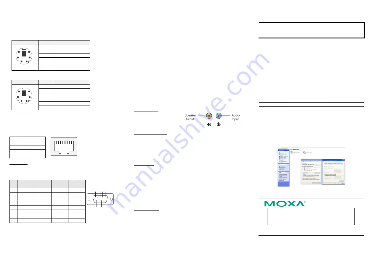
8. Configuring the Ethernet Interface
Follow these steps to configure the Ethernet interface:
Step 1:
[My Device]
Æ
[Control panel]
Æ
[Network Connections]
to
enter the network setting page.
Step 2: Right-Click the LAN interface (e.g., Local Area Connection 2) to
configure and click property. A configuration window will pop up
Step 3: After inputting the proper IP address and netmask, click
OK
.
Click here for online support:
www.moxa.com/support
The Americas: +1-714-528-6777 (toll-free: 1-888-669-2872)
Europe: +49-89-3 70 03 99-0
Asia-Pacific: +886-2-8919-1230
China: +86-21-5258-9955 (toll-free: 800-820-5036)
©
2008 Moxa Inc., all rights reserved.
Reproduction without permission is prohibited.


