background image

LITESPORT OWNERS MANUAL 

2  

Version 1.01 


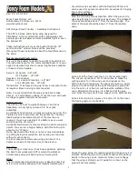
AMENDMENTS 

Version 

Date 

Changes 

1.00 

20/08/2003 

Created original owners manual. 

1.01 

5/05/2004 


Added Zoom Upright Assembly Drawing 


Updated Stability System instructions 

Summary of Contents for LITESPORT 4

Page 1: ...Moyes Delta Gliders Pty Ltd Version 1 01 LITESPORT owners manual...

Page 2: ......

Page 3: ...ons 5 Operating Limitations 6 Disclaimer 7 Assembly Procedures 8 Pre Flight Check 16 De Rigging the Litesport 18 Flying The Moyes Litesport 22 Tuning Hints 26 Glider Care 30 Maintenance Schedule 32 Sa...

Page 4: ...ESPORT OWNERS MANUAL 2 Version 1 01 AMENDMENTS Version Date Changes 1 00 20 08 2003 Created original owners manual 1 01 5 05 2004 Added Zoom Upright Assembly Drawing Updated Stability System instructi...

Page 5: ...nd topless gliders providing a very capable glider for either the advancing pilot or the an advanced recreational pilot Since 1967 Moyes Delta Gliders has strived to be on the cutting edge of developi...

Page 6: ...better turn coordination compared to conventional designs With the VG fully engaged the fibreglass tip produces a tighter mainsail and more desirable washout distribution The pitch stability system u...

Page 7: ...Weight 68 109 kg 150 240 lb 79 129 kg 175 285 lb Packed Length 4950 mm 16 2 ft 5150 mm 16 9 ft Short Packed Length 4330mm 14 2 ft 4500 mm 14 8 ft C of G Front of Keel 1390 mm 54 7 inches 1430 mm 56 3...

Page 8: ...t be flown in excess of the placarded VNE or VA VNE speed never to exceed 53mph 85kph VA maximum rough air manoeuvring speed 46mph 74kph Stall speed with maximum pilot weight Less than 25mph 40kph Max...

Page 9: ...o warranty is made or implied of any kind against accidents bodily injury or death Operations such as aerobatic manoeuvres or erratic pilot technique may produce equipment failure This glider is not c...

Page 10: ...labelled left and right 1 x batten set red left green right blue undersurface 1 x speed bar 2 x tip bags 4 x padding pieces A frame top bottom keel sleeve king post top 1 x Snack Pack with owners manu...

Page 11: ...s of the leading edge 4 Secure the sail by attaching the tip webbing to the end of the leading edge using the clevis pin and safety ring supplied Insert the pin through the webbing and into the bottom...

Page 12: ...p ASSEMBLY PROCEDURES 1 Place the glider on the ground zipper facing up Open the bag undo the ties and remove the A frame bottom padding and battens 2 Assembly the A Frame Picture 4 Standard uprights...

Page 13: ...ring of the lower front wires into the Bailey Block making sure that the spring is firmly closed and the wires are not twisted Picture 6 Attaching the front wires to the Bailey Block 6 Insert the nose...

Page 14: ...nd that the shackle is secured within the Bailey Block Attach the king post rear wire behind the shackle in the Bailey Block In strong winds the glider can be difficult to tension Have a helper gently...

Page 15: ...s 1 6 moving from the centre of the wing towards the mid span Use light force when inserting the battens as this will greatly extend the longevity of the batten pockets Red tipped battens are for the...

Page 16: ...ctory but may need to be readjusted upon initial assembly The batten tips simply screw into the end of the batten therefore the batten tension can be adjusted by either screwing the tip in or out Pict...

Page 17: ...tly to secure it within the pocket 18 Fit the nose fairing using the attached Velcro patches Picture 14 Insert the mylar tab on the nose fairing under the leading edge Picture 15 Pull the top rear of...

Page 18: ...ted perpendicular to the keel and is free from the nose batten pocket Check the hang loop and backup 3 Open the under surface zipper and inspect the cross bar limiting wire Pull the VG on and off to c...

Page 19: ...ed by the Bailey Block bolt 13 Moving across to the other wing repeat the process as you work your way back to the nose of the glider Carefully check the front bottom wires and nose catch before inspe...

Page 20: ...towards the outer wing 3 Remove the nose cone unload the nose batten and remove all top battens and all the under surface battens 4 Rotate the dingle dangle so that it is parallel to the keel and att...

Page 21: ...roll the sail until tightly rolled around leading edge Fit the sail and the outer dive strut into the boot 7 Replace the keel if the glider has been disassembled with the keel removed 8 De tension th...

Page 22: ...nd roll the sail parallel to the transversal battens Picture 20 Roll the sail 13 Attach the sail ties loosely around glider going from the wing tip to nose Then tighten the ties moving from nose to wi...

Page 23: ...m over the control frame enclosing the frame with the leading edge pockets Fit the padding provided to the bottom of the control frame Tuck all wires and bars neatly inside the sail Pull the hang loop...

Page 24: ...commended For light or nil wind take offs some VG can help the glider lift sooner making launching easier This is especially helpful for take offs on shallow slopes as the glider s increased performan...

Page 25: ...is possible to thermal the Litesport with up to 1 3 VG and experience a noticeable gain in climb rate However when the VG is pulled 1 3 tight the Litesport requires more high siding especially at low...

Page 26: ...ises the nose and even if the pilot holds the control bar in position the glider will climb and quickly lose airspeed It is at this point that the glider is vulnerable to tumbling It is therefore para...

Page 27: ...ty by entering this foreseen turbulence with an appropriate VG setting Flying the Litesport in Rain Flying in rain can cause significant changes to the behaviour of the glider It is strongly advised t...

Page 28: ...uction of pitch pressure Most competition pilots prefer to fly with a more rearward CG location Pilots favour this as they can experience less push out pressure when circling and thus the glider becom...

Page 29: ...ely by uneven dive strut heights To fix this kind of turn you should adjust the dive struts If you have a gentle left turn the first step is to raise the right side dive strut 1 4 turn This is best do...

Page 30: ...n slightly the glider will become less stable and performance gains are absolutely minimal Simply DO NOT LOWER THE DIVE STRUTS Eccentric Rings Adjustment The Litesport has a series of eccentric rings...

Page 31: ...ction leading edge Before attempting this it is best to consult the relevant assembly drawing in this manual Remove the sail retaining clevis pin at the back section end and the 3 16 pin or possibly b...

Page 32: ...ess point or along the trailing edge it will not tend to run or expand Sun and exposure to the elements will deteriorate the sail more rapidly than hours of flying It is important to minimise exposure...

Page 33: ...al Fliers The Litesport uses thin walled 7075T6 tubing throughout the airframe which is considerably more vulnerable to corrosion than the 6061 alloy used on previous gliders If any tubing is ever dir...

Page 34: ...very 100 Hours or annually This inspection is best carried out by your local Moyes dealer or the Moyes factory The sail must be removed allowing for all components to be exposed and thoroughly examine...

Page 35: ...e tie at the nose of sail 4 Disconnect the luff line and undo the clevis pin on both sides to release the top side wires from the leading edges 5 Disconnect the bottom side wires from the bottom of th...

Page 36: ...res such as ladders With the VG system fully applied tie a piece of thin thread between the two number nine batten ends ensuring the string it taut The string should be positioned under the keel Obtai...

Page 37: ...l if string line falls below the keel measure from bottom of keel and add the diameter of the keel 42mm IMPORTANT Measurements are the same for both Mylar and Powerrib models NOTE STEP TWO Align Bolt...

Page 38: ...NUAL 36 Version 1 01 PURCHASE RECORD Please complete this section for future reference Glider Model and Size Purchase Date Serial Number Moyes Dealer purchased from Dealer Address MAINTENANCE LOG Date...

Page 39: ...r Medium Plastic Washer 10 Stainless Steel Screw AN4 Half Nut Bottom Nose Plate Bailey Block AN4 Half Nut Medium Plastic Washer Medium Plastic Washer 10 Screw With Spacer AN4 33A Bolt Small Plastic Wa...

Page 40: ...LITESPORT OWNERS MANUAL 38 Version 1 01...

Page 41: ...le Dangle Bottom Dingle Dangle Top AN5 Half Nut AN4 Half Nut Pulley 5 32 Screws Keel Tube AN4 31A Bolt AN4 12A bolt AN5 34A Bolt Plastic Spacers Towed In Plastic Spacers Towed In AN4 Half Nut Note Sus...

Page 42: ...LITESPORT OWNERS MANUAL 40 Version 1 01...

Page 43: ...LITESPORT OWNERS MANUAL Version 1 01 41...

Page 44: ...LITESPORT OWNERS MANUAL 42 Version 1 01...

Page 45: ...LITESPORT OWNERS MANUAL Version 1 01 43...

Page 46: ...Right Upright Note Top VG Rope must go on the inside of the Trimmer Sheave Note Bottom VG Rope must go on the outside of the pulley Pulley Double Bryco Pulley Double Bryco Safety Ring Safety Ring Cle...

Page 47: ...S MANUAL Version 1 01 45 AN4 21A Bolt Washer AN4 Nut Half Nut AN4 12A Bolt Half Nut Bottom Kingpost Mounting Bracket Pulley Top Kingpost Mounting Bracket Stainless Steel Washers Bolt Plastic Spacer Co...

Page 48: ...tom Pulley and Wire Zoom Top Fitting Specify Left or Right when ordering 2C25 Pin Safety Clip Bottom Fitting Stainless Steel Pin Harken Pulley Aluminium Washer Stainless Steel Sleeve Stainless Steel P...

Reviews: