23
7. Operation
7.1.
PLC Set Up and Settings
7.1.1. PLC Initial Set Up
After connecting all hoses and power, the Purge can be turned on and the PLC set up.
1. If there is a screen in the tank that separates the clean and dirty side, be sure to
clean the screen if installing on a machine tool that has already been run.
Obstructions between the clean and dirty side can prevent proper operation.
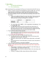
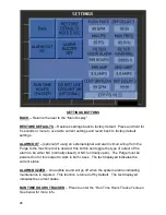
2. Go into the settings on the PLC and confirm the amp settings match your motor
name plate.
•
These are the default settings for min and max amps. These are average
values that will allow the unit to get started. Changing these values to
match your motor will allow the Purge to run at its best.
LOW VOLT
HIGH VOLT
MIN AMP
1.5
.5
MAX AMP
8.5
4.0
•
The motor plate
will list “AMPS” or “FLA” depending on manufacturer. This
is the MAX AMP value.
•
The MIN AMP should be set to the current the motor pulls when it is
sucking air. This can be found by running the motor for a few seconds
before hooking up the hoses, or if it has already been installed, by raising
the dip tube out of the tank to make the pump suck air briefly.
3. Turn on all of the coolant pumps in the tank
•
You should see the coolant flowing into the clean section from the dirty
section through the screen.
The coolant on the clean side of the screen
will be lower than the dirty side.
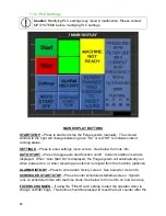
4. From the main screen, start the Purge and wait 30 seconds.
•
The first time you turn on the Purge, there will be air in the hose which
might alarm out the machine. This is OK.
•
If it alarms, clear the alarm and restart from the main screen until coolant
flows.
•
If you get more than 5 consecutive alarms, check for loose connections or
blocked inlet.
•
If the problem persists, contact
MP SYSTEMS
.
5. Check to make sure the coolant is flowing through the screen in the
reverse
direction
.
The coolant in the clean side should now be level with or higher than
the dirty side.
•
If the coolant is
not
flowing in reverse,
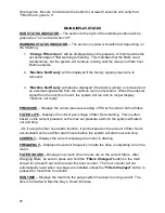
hit “STOP” on the PLC Screen, go
to “SETTINGS”, and increase the FLOW value.
•
Once the FLOW Value has been entered, go back to the main screen and
select “START”.
•
Continue to increase the flow value until reverse flow is achieved.
Summary of Contents for PURGE Series
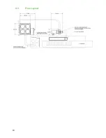
Page 15: ...10 4 3 Floor Layout ...
Page 44: ...39 10 Schematics and Diagrams 10 1 1 POWER SCHEMATIC 208 230V ...
Page 45: ...40 10 1 2 POWER SCHEMATIC 480V ...
Page 46: ...41 10 2 CONTROL SCHEMATIC ...
Page 47: ...42 10 3 FLOW DIAGRAM ...

