TOM McEWEN
1
NON PLATED
1
PLATED
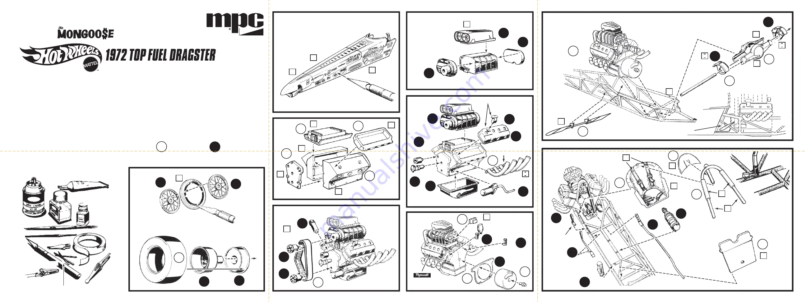
Shown below are an assortment of supplies and
tools which will help you with your construction.
MODELERS KNIFE
TUBE CEMENT
LIQUID CEMENT
BRUSH PAINT
ART BRUSHES
TWEEZERS
TOOTHPICKS
ALLIGATOR CLIPS
FILES
BLADES
TAPE
SPRAY PAINT
FOLLOW THE NUMBERS STEP-BY-STEP
WORK CAREFULLY. TAKE YOUR TIME.
ASSEMBLY PROCEDURE NUMBERS
Before you begin building, look over the instructions carefully. Following
the procedure given, test-fit parts together without cementing. This way
you will be more familiar with the location of parts when it becomes time
to use cement.
For removing small parts from the “runners” it is best to use a
modelers knife, do not attempt to “twist” them off.
The highest quality styrene plastic goes into the making of each MPC
®
model. Only cement and paint designed for styrene plastic should be
used. Before joining parts, trim off excess plastic or “flash.” Scrape
plating from chromed parts where they are to be joined with other parts.
Be careful not to get cement on exposed areas. To join parts, use
cement sparingly. Apply cement to very small parts with a toothpick.
When painting your model it is best to cement all non-chromed
accessories to the body and paint the whole unit at one time.
You should have no trouble assembling your kit if the instructions are
followed properly.
READ THIS FIRST:
105 & 142
Assemble two as shown.
ONE FOR
EACH SIDE
ONE FOR EACH SIDE
METAL AXLE
HEAD SHIELD
FORWARD BULKHEAD
FREON FIRE
EXTINGUISHER
FUEL LINE
HAND
CONTROLS
ONE FOR
EACH SIDE
HAND BRAKE
124
123
10
18
6
19
12
120
132
121
ACCELERATOR
See detail (A) for
positive location.
Locate through hole in
forward bulkhead.
DISC
BRAKES
DISC BRAKES
DO NOT
CEMENT
Slide metal axle through
assembled rear end.
ONE FOR EACH SIDE
BREATHERS
108
HEADERS
24
17
EXPANSION TANK
110
BLOCKS VENTS
109
23
118
20
BLOW SHIELD
ASSEMBLY
112
IDLER
133
FUEL PUMP
134
OIL PUMP AND FILTER
142
107
ROCKER COVERS
FRONT
WHEELS
DECALS
REAR WHEELS
Remove centers
carefully.
BLOWER
REAR END
COCKPIT AND CONTROLS
DETAIL (A)
ENGINE BLOCK
Decals shown in place.
10
138
138
106
111
MAGNETO
BLOWER DRIVE
113
14
114
13
13
15
16
22
115
141
141
21
21
140
DECAL BOTH SIDES
1
1
1
1
4
4
6
8
2
3
4
3
1
1
1
1
1
2
2
2
2
8
9
2
2
3
3
3
3
3
3
4
4
4
5
5
6
7
2
A
B
C
H
I
D
F
G
E
Tape body panels together from
inside. Apply decals. When decals
are dry, cut to separate panels.
2
5
5
6
6
7
A
A
A
A
A
B
C
C
C
C
F
H
H
K
I
I
I
M855-200
U
U
U
U
U
U
G
G
2
3
4
SLIDE SIDE WINGS THROUGH CHASSIS AND GLUE
TO STRUT AS SHOWN. NOTE POSITION BETWEEN
FUEL LINE AND DRIVER SEAT


