background image

OPERATING AND SERVICE MANUAL

  XR SERIES III


DC POWER SUPPLIES

Summary of Contents for XR III series

Page 1: ...OPERATING AND SERVICE MANUAL XR SERIES III DC POWER SUPPLIES...

Page 2: ......

Page 3: ...MAGNA POWER ELECTRONICS INC 39 ROYAL ROAD FLEMINGTON NJ 08822 February 20 2012...

Page 4: ......

Page 5: ...ut power is de energized prior to connecting or disconnecting the input and output power cables Caution Lethal voltages may be present inside the power supply even when the ac input voltage is disconn...

Page 6: ...product will be treated on a non warranty basis All electrical commercial supply parts and items not manufactured by Magna Power Electronics Inc shall carry the warranty of the original manufacturer...

Page 7: ...ment When referring to this equipment always include the model and serial number RETURNING EQUIPMENT Before returning any equipment to the factory the following steps should be taken 1 Contact our tec...

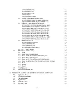
Page 8: ...1 2 6 2 2 XRC Series Models 22 3 0 OPERATION 25 3 1 Front Panel Commands 25 3 1 1 Run Mode Commands 25 3 1 2 Set Point Commands 26 3 1 3 Configuration Commands 28 3 1 4 Calibration Commands 31 3 2 Mod...

Page 9: ...stem 53 4 3 2 1 MEAS VOLT 53 4 3 2 2 MEAS CURR 54 4 3 3 System Subsystem 54 4 3 3 1 SYST VERS 54 4 3 3 2 SYST ERR 54 4 3 4 Status Subsystem 55 4 3 4 1 Operation Register 55 4 3 4 2 Questionable Regist...

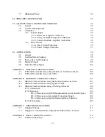
Page 10: ...tional Ethernet only 69 4 3 12 9 NET DHCP Optional Ethernet only 69 4 3 13 Recall Subsystem 69 4 3 14 1 MOD TYPE SEL 70 4 3 14 2 MOD TABL 71 4 3 14 3 MOD SAVE 72 4 3 14 4 MOD TABL LOAD 73 4 3 15 SCPI...

Page 11: ...488 COMMUNICATIONS 105 A 1 IEEE 488 Communications using the Remote Interface Software 105 A 2 IEEE 488 Communications with MAX 105 APPENDIX B ETHERNET COMMUNICATIONS 107 B 1 Ethernet Communications u...

Page 12: ...D 2 HyperTerminal Setup 114 D 3 485DSS Address Command 115 D 4 485DSS Communications using HyperTerminal 115 viii...

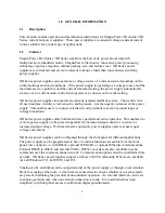
Page 13: ...es users to connect external circuitry without concern of ground loops or voltage breakdown XR Series power supplies offer both master slave parallel and series operation This enables two or more powe...

Page 14: ...ar connector or with RS232 optional IEEE 488 or optional Ethernet communications XR Series power supplies with XR Version front panels are well suited for industrial and laboratory applications XR Ser...

Page 15: ...T set point Voltage current output Internal external control Alarms Rotary external remote programming Remote sense enabled REAR PANEL CONTROLS Voltage current set point OVT OCT set point Modulation s...

Page 16: ...risk of electric shock Caution risk of danger Protective conductor terminal Three phase alternating current 1 4 Power Requirements XR Series power supplies are manufactured to operate on 208 240 V 380...

Page 17: ...cale Load regulation Voltage Mode 0 01 of full scale Current Mode 0 04 of full scale Stability 0 10 for 8 hours after 30 minute warm up Maximum Slew Rate for standard models 100 ms for an output volta...

Page 18: ...to 100 output Current set point 0 to 10 0 Vdc for 0 to 100 output Over voltage trip set point 0 to 10 0 Vdc for 0 to 110 output Over current trip set point 0 to 10 0 Vdc for 0 to 110 output Modulation...

Page 19: ...nterface connectors see figure 1 1 and Tables 1 5 1 6 1 7 1 8 and 1 9 for details JS1 37 pin D Subminiature female JS2 2 terminal 6 32 screw connector JS3 9 pin D Subminiature female JS4 optional 24 p...

Page 20: ...arge EN61000 4 3 Radiated Susceptibility EN61000 4 4 Electrical Fast Transient Burst EN61000 4 6 Conducted Susceptibility EN61000 4 8 Magnetics EN61000 4 11 Voltage Dips Interruptions Optional Etherne...

Page 21: ...240 SP 208 240 380 415 440 480 See Table 1 3 Note 1 Multiple options can be specified as indicated Table 1 3 OPTIONS TERM DEFINITION EMI WC HS LXI GPIB USB RS485 EW EMI Filter Water Cooling High Slew...

Page 22: ...18 19 20 21 22 23 24 25 26 EXT CTL RESERVE RESERVE START CLEAR STOP REF GND 10V REF IREF EXT TIREF EXT IO2 VMOD 5V 27 28 29 30 31 32 33 34 35 36 37 PGM LINE STANDBY PHASE LOSS VOLT CTL RESERVE OCT INT...

Page 23: ...a Valid NRFD Not Ready For Data NDAC Not Data Accepted IFC Interface Clear SRQ Service Request ATN Attention Shield 13 14 15 16 17 18 19 20 21 22 23 24 DIO5 Data line DIO6 Data line DIO7 Data line DIO...

Page 24: ...OUTPUT PARAMETERS OUTPUT VOLTAGE RANGE Vdc OUTPUT POWER RANGE kW OUTPUT CAPACITANCE F RIPPLE Vrms 5 10 16 20 32 40 80 100 400 500 600 800 1000 2 8 13200 4080 2340 1170 240 160 80 56 56 52 50 50 70 1...

Page 25: ...125 160 200 250 375 400 500 600 800 1000 375 200 125 100 62 50 40 25 20 16 12 10 8 0 5 3 5 0 4 0 3 3 2 5 2 0 50 40 35 40 40 40 50 60 60 100 120 125 130 170 190 220 250 300 350 86 86 86 86 86 87 87 87...

Page 26: ...80 100 125 160 200 250 375 400 500 600 800 1000 375 250 200 124 100 80 50 40 32 24 20 16 10 6 10 0 8 0 6 6 5 0 4 0 40 35 40 40 40 50 60 60 100 120 125 130 170 190 220 250 300 350 86 86 86 86 87 87 87...

Page 27: ...200 250 375 400 500 600 800 1000 375 300 186 150 120 75 60 48 36 30 24 15 9 15 0 12 0 9 9 7 5 6 0 35 40 40 40 50 60 60 100 120 125 130 170 190 220 250 300 350 86 86 86 87 87 87 87 87 87 87 88 88 88 88...

Page 28: ...160 200 250 375 400 500 600 800 1000 375 250 200 160 100 80 64 50 40 32 21 3 20 0 16 0 13 3 10 0 8 0 60 60 60 70 80 80 120 125 120 140 200 220 240 280 320 380 86 86 87 87 87 87 87 87 87 88 88 88 88 8...

Page 29: ...LTAGE DC CURRENT CONFIGURATON MODE PWR ELECTRONICS MAGNA POWER B 3 INPUT OUTPUT NEG A C GND POS JS1 JS3 24 000 0 234 3 469 0 328 19 000 1 000 6 312 0 875 1 966 AIR INTAKE BOTH SIDES 0 250X1 000 SILVER...

Page 30: ...s or blowers to remove heat generated by the power supplies The manufacturer recommends fresh air intake at the bottom of the cabinet and exhaust at the top Fans and blowers should be rated at 300 CFM...

Page 31: ...fter connections are made screw the four standoffs into the back panel and place the protective shield over the connections Caution Make sure connections are tight to avoid overheating of the bus bars...

Page 32: ...CM 350 MCM 25 30 40 60 80 105 120 140 165 195 225 260 300 340 375 420 30 35 50 70 95 125 145 170 195 230 265 310 360 405 445 505 30 40 55 75 100 135 160 185 215 250 290 335 390 440 485 550 35 40 55 80...

Page 33: ...heck be made shortly after unpacking the supply Press the start switch and advance the current control one turn clockwise The power and voltage control indicators should light Increase the voltage set...

Page 34: ...e over current trip set point The over current trip OCT indicator should turn on the power and current control indicators should turn off and the supply should shut down Press the clear key Now set th...

Page 35: ...tches main power on and off FUNCTION KEYS MENU selects function ITEM selects item within function V I DIS displays voltage and current settings TRIP DIS displays OVT and OCT settings CLEAR clears sett...

Page 36: ...Figure 2 2 XRC Series controls and indicators PWR ELECTRONICS MAGNA POWER Energizes control circuits without turning on main power 24...

Page 37: ...either the standby alarm or power mode state Configuration commands include local or remote sense internal and or external control remote interlock and mode of set point input There are three choices...

Page 38: ...ual output current will be less than the current set point If the power supply is operating in current mode then the actual output current will be close to the current set point and the actual output...

Page 39: ...sing and holding the OVT DISPLAY INCREMENTS OVT DISPLAY DECREM ENTS PS RETURNS TONORMAL OPERA TION PS RETURNS TONORMAL OPERA TION OVT DISPLAY ENTERED AS OVTSET POINT ENTER CLEAR CLEAR 5 OVT AND OCT LE...

Page 40: ...or loc LED is flashing To select press enter or to deselect press clear Remote sense allows the output voltage to be sensed at the load rather than at the output terminals of the power supply This fe...

Page 41: ...ES EXT CTL LED FLASHES ROTARY LEDFLASHE S EXT PGM LED FLASHES REMOTE LED FLASHE S INTERLOCK LED FLASHES ENTER CLEAR ENABLES INT CTL INTCTL LED ON INTCTL LED OFF DISABLES INT CTL 1 ENABLES INTERNAL STA...

Page 42: ...P TRIP SET CLEAR V I SET conFFLASHES IN VOLT DISPLAY STANDBY MODE ONLY CAL FLASHES IN VOLT DISPLAY OCTDISPLAYED IN CUR DISPLAY OVT DISPLAYED IN VOLTDISPLAY OCTLED FLASHES OVT LED FLASHES ITEM ROTARY A...

Page 43: ...nately flash in the left digit of the current display Potentiometer 1 adjusts the gain of the voltage feedback amplifier potentiometer 2 adjusts the input offset voltage of the voltage feedback amplif...

Page 44: ...N VOLTDISPLAY DISPLAY 3 INMEMORY DISPLAY DISPLAY P4 SETTING IN VOLTDISPLAY DISPLAY 4 INMEMORY DISPLAY DISPLAY IO IN CUR DISPLAY DISPLAY 5 INMEMORY DISPLAY DISPLAY P5 SETTING IN CUR DISPLAY DISPLAY VO...

Page 45: ...to the factory default settings To exit the calibration menu press the item key until rEt return appears in the voltage display Press the enter key to exit the calibration menu 3 2 Modes of Operation...

Page 46: ...l of the load and connect terminal 1 of JS2 to the negative terminal of the load Figure 3 12 illustrates standard output sensing and remote output sensing Enabling remote sense activates the remote se...

Page 47: ...supplies allow voltage current voltage trip and current trip to be programmed from a remote location Programming can be accomplished either by resistive voltage or current programming circuits Figure...

Page 48: ...ge and c current programming 1 P OJS1 10 00V REF REFGND 3 RP 21 a b VP IP 10K c REF GND REF VREF EXT VREF VREF VREF EXT REF GND 21 3 REF GND REF 10 00V P OJS1 1 1 P O JS1 10 00V REF REF GND 3 21 REFGN...

Page 49: ...gl program line LED will light and the power supply will turn off Table 3 1 EXTERNAL PROGRAMMING PARAMETERS TERM PARM DESCRIPTION INPUT RANGE V OUTPUT RANGE 3 22 4 23 VREF EXT IREF EXT TVREF EXT TIREF...

Page 50: ...p have been calibrated to trip at 110 full scale output voltage and current with 10 0 V inputs at the external reference input terminals If the applied voltage at any input is greater than 12 50 V the...

Page 51: ...ns include thermal overload interlock power standby phase loss program line over voltage and over current All diagnostic indicators have memory retention which saves the fault condition until the powe...

Page 52: ...input control lines Figure 3 16 Digital output control lines ALM 13 33 INT CTL EXTCTL 14 OCT 32 STANDBY 28 THL 9 PGL 27 POWER 8 OVT 34 MONITORING LINES P OJS1 30 11 VOLT CTL CUR CTL 10 29 LOC PHL 7 GN...

Page 53: ...ary over current trip diagnostic provides protection of internal circuitry due to abnormal line and load conditions or due to failed internal circuitry This over current trip condition requires the co...

Page 54: ...ry The control cable can be fabricated by the user or purchased as an option UID46 from the factory These connections perform the following functions 1 The current monitoring voltage IO2 on the master...

Page 55: ...eration Two or more power supplies can be connected in series to obtain a total output voltage greater than that available from one power supply The total output voltage is the sum of the output volta...

Page 56: ...oltage VO2 on the master power supply connects to the external voltage set point input on the slave power supply This makes the slave power supply operate at the same voltage output as the master powe...

Page 57: ...ross the output terminals of the power supply These capacitors help to supply high current pulses of short duration during constant voltage operation Any capacitance added externally will improve the...

Page 58: ...t point reference TVREF Over voltage trip reference TIREF Over current trip reference VMOD Modulation set point voltage DIGITAL INPUT CONTROL LINES STOP Remote stop START Remote start CLEAR Clear INTE...

Page 59: ...lears setting or resets fault condition ITEM specific item within menu selection V I DIS displays voltage and current set point TRIP DIS displays over voltage trip and over current trip set point REM...

Page 60: ...tors For additional documentation and details on using the IVI COM driver see the driver s included help file MPEIVI chm The RS232 port connector JS3 located on the rear panel allows all of the front...

Page 61: ...of the power supply open enter the command VOLT xx where xx is 50 of rated voltage and press enter Press the display key on the front panel of the power supply and verify that the set point is 50 of...

Page 62: ...d remains in effect until the trigger subsystem receives a trigger or is aborted with an ABORt command In order for VOLT TRIG to be executed the trigger subsystem must be initiated see Initiate Subsys...

Page 63: ...s disabled and the Questionable Condition status register OV bit is set see Table 4 2 An over voltage trip condition can be cleared with the OUTP PROT CLE command after the condition that caused the O...

Page 64: ...R 200 CURRENT LEVEL MIN CURRENT LEVEL IMMEDIATE AMPLITUDE 2 5 CURR TRIG 20 CURRENT LEVEL TRIGGERED 20 Query Syntax SOURce CURRent LEVel IMMediate AMPLitude SOURce CURRent LEVel IMMediate AMPLitude MAX...

Page 65: ...top as if a stop command condition see OUTP STOP occurred When a 9998 is detected the following memory location will be zero When 9999 is detected the power supply will operate at that memory state in...

Page 66: ...m VERSion Examples SYST VERS SYSTEM VERSION Returned Parameters Firmware Rev XX Y Hardware Rev XX Y Related Commands None 4 3 3 2 SYST ERR The SYST ERR query returns the error messages that have occur...

Page 67: ...ue of the Operation Register which is a read only register that holds the real time unlatched condition of the operational status of the power supply The bit configuration of the Operation Register is...

Page 68: ...Tripped 3 8 PGM Program Line Protection Tripped 4 16 OT Over Temperature Protection Tripped 5 32 FUSE Fuse Protection Tripped 6 64 NU Not used 7 128 ALM Alarm Protection Tripped 8 256 ILOC Interlock...

Page 69: ...or use the front panel start switch The ARM light will blink after the start command If this process reaches the upper memory limit memory location 99 the following memory location will revert back to...

Page 70: ...There are seven alarm latches namely interlock program line phase balance thermal over voltage trip over current trip and fuse When a fault is detected the power supply is rendered to an alarm state...

Page 71: ...nabled for subsequent triggers As soon as it is cleared the WTG bit is again set to 1 Command Syntax TRIGger IMMediate Examples TRIG TRIGGER IMMEDIATE Query Syntax None Related Commands ABOR CURR TRIG...

Page 72: ...ve up to 100 characters Command Syntax CALibrate IDN string Parameters Company Name Power Supply Model S N string format where Company Name Magna Power Electronics Inc Power Supply Model PS Type PSVol...

Page 73: ...T NR1 NR1 Examples CAIBRATE POT 1 123 CAL POT 5 11 Query Syntax CALibrate POT NR1 Returned Parameters NR1 Related Commands None 4 3 9 4 CAL SCAL VOLT This command sets the voltage scale factor for the...

Page 74: ...tch the scaling factor set with hardware on the control board Command Syntax CALibrate SCALe INPut NRf Examples CALIBRATE SCALE INPUT 10 0 CAL SCAL INP 10 0 Query Syntax CALibrate SCALe INPut Returned...

Page 75: ...monitors the voltage at the output terminals of the power supply The query command REM SENS returns the state of the sense lines Command Syntax CONFigure REMote SENSe bool Parameters 0 OFF 1 ON Examp...

Page 76: ...Figure CONTrol EXTernal Returned Parameters 0 1 Related Commands None 4 3 10 4 INTE This command enables or disables the external interlock feature Interlock described in Section 3 6 is used for appli...

Page 77: ...tional GPIB only This query reads the firmware version of the GPIB communication module Command Syntax none Query Syntax SYSTem COMMunicate GPIB VERSion Parameters none Examples SYST COMM GPIB VERS GP...

Page 78: ...mands None 4 3 12 2 NET MAC Optional Ethernet only This query returns the MAC address of the Ethernet module MAC address consist of two number groups the first three bytes are known as the Organizatio...

Page 79: ...100 Command Syntax SYSTem COMMunicate NETwork ADDRess string Parameters IP address is represented with 4 bytes each having a range of 0 255 separated by dots Examples SYSTem COMM NET ADDR 192 168 10...

Page 80: ...ated by dots Examples SYSTem COMM NET SUBNet 255 255 255 128 NET SUBNet 255 255 255 128 Query Syntax SYSTem COMMunicate NETwork SUBNet Returned Parameters string Related Commands NET MAC NET ADDR NET...

Page 81: ...odule If DHCP is set to 1 the module will allow its IP address to be automatically set by the DHCP server on the network If DHCP is set to 0 the IP address is set according to Section 4 3 12 4 The fac...

Page 82: ...oltage or output current When the control input is set to 1 VMOD selects the modulation table to adjust output voltage When control input is set to 2 VMOD selects the modulation table adjust to output...

Page 83: ...n table described in Section 4 3 14 1 The feature allows the user to program nonlinear output voltage and current profiles to fit their application needs such as source emulation or output adjustments...

Page 84: ...4 Description Row VMOD Mod Loc Acceptable Range 1 to 50 0 0 TO 10 0 1000 0 to 1000 0 0 to 1 While the table will store any value within the acceptable range the power supply is limited by its output v...

Page 85: ...d tables and simultaneous change the power supply s output operating point Command Syntax MOD TABL LOAD NRf NRf Examples MOD TABL LOAD MODulation TABLe LOAD MODulation TABL LOAD 93 4 30 3 Query Syntax...

Page 86: ...query discussed in Section 4 5 4 bit 6 will be 1 if there are any conditions requiring service The STB is masked by the Service Request Enable Register SRE to allow the user to mask specific or all e...

Page 87: ...r is cleared The bit configuration of the ESR is the same as the Event Status Enable Register ESE The return parameter is weighted as shown in Table 4 6 The Power On Bit PON is set every time the powe...

Page 88: ...Figure 4 1 Status Byte Generation Figure 4 2 ESE and ESR Generation 76...

Page 89: ...te Register STB A 1 in the bit position enables the corresponding event All of the enabled events of the ESE are logically OR d to cause the ESB of the STB to be set Command Syntax ESE NR1 Example ESE...

Page 90: ...Byte Register bit All Status Byte Register enabled bits are then logically OR d and placed in bit 6 of the Status Byte Register When SRE is cleared by programming it with 0 the power supply cannot gen...

Page 91: ...00 memory locations For XR Series power supplies only memory location 0 is available The following power supply parameters are stored by SAV VOLT LEV IMM CURR LEV IMM VOLT PROT LEV CURR PROT LEV PER C...

Page 92: ...VOLT LEV IMM 0 VOLT LEV TRIG 0 PER 0 INIT CONT OFF VOLT PROT LEV 110 of MAX CURR PROT LEV 110 of MAX RST also forces an ABORt command Command Syntax RST Query Syntax None Related Commands None 4 6 Err...

Page 93: ...ed Command Set Commands and queries described in this Section 4 0 require the power supply to be configured for remote operation There are instances when the power supply may be configured for rotary...

Page 94: ...d INIT CONT Calibrate CAL IDN CAL PASS CAL POT CAL SCAL VOLT CAL SCAL CURR CAL DEF CAL STOP Configure REM SENS CONT INT CONT EXT INTE SETPT GPIB Communications GPIB VER GPIB ADDR Ethernet Communicatio...

Page 95: ...IEEE Standard CLS ESR ESE STB SRE IDN SAV RCL RST Notes 1 C command Q query 83...

Page 96: ...r XR or XRC Series power supplies 2 Communications interface RS232 RS485 optional GPIB IEEE 488 optional TCP IP Ethernet simulated or others depending on future developments Figure 5 1 displays the Ap...

Page 97: ...Figure 5 1 Configuration setup Figure 5 2 GPIB communications setup 85...

Page 98: ...graphically represents the six internal registers of the power supply Register functions as covered in the previous Chapter are briefly summarized below 1 Operation register oper indicates the power...

Page 99: ...Figure 5 4 Virtual Control Panel Figure 5 5 Command Panel 87...

Page 100: ...ister value in decimal hex and binary formats The Enter Value in Selected Format frame allows the user to specify the format for data entry The Output frame shows all communications with the power sup...

Page 101: ...ll display the address in memory being erased After the entire memory is erased the Status frame will display Loading and the Current Address frame will display the address in memory being loaded The...

Page 102: ...Figure 5 7 Calibration Panel Figure 5 8 Firmware Panel 90...

Page 103: ...Figure 5 9 Modulation Panel 91...

Page 104: ...iltering harmonics on the dc bus As illustrated chopper output current is monitored for balancing and for sensing overload current conditions The polyphase chopper has been engineered to eliminate har...

Page 105: ...E TRANSFORMER POWER BOARD GATE DRIVER BOARD CONTROL RECTIFIERS PIE FILTER DISPLAY BOARD INTERFACE ASS Y DC VOLTAGE CURRENT 208 380 480 V 3 PHASE CURRENT FED INVERTER INDUCTORS DC LINK EMI FILTER FUSES...

Page 106: ...control board which is referenced to earth ground contains optically isolated amplifiers to sense output voltage and current This circuitry allows the output to be referenced 1000 Vdc above earth gro...

Page 107: ...easuring primary circuitry since this is at line potential 7 2 Trouble Shooting Guide 1 Fuse F1 F2 or F3 blows when the power supply is turned on Power supply has a short on the primary side a Check d...

Page 108: ...y and adjust potentiometer P1 until the output voltage matches the set point voltage Now set the output voltage to its full scale rating and measure the output voltage Adjust potentiometer P1 to equal...

Page 109: ...ctory Gross misadjustment can cause chopper and inverter failure Connect the power supply to an adjustable ac source and connect an ac voltmeter to monitor the voltage applied to the input terminals T...

Page 110: ...voltage control and set the modulation type to 1 Figure 8 1 illustrates the hardware connection and Section 4 3 14 describes application of the modulation subsystem With this configuration output vol...

Page 111: ...Figure 8 1 Leadless remote sensing Figure 8 2 IV characteristics for a typical photovoltaic array IO2 24 REF GND 25 P O JS1 VMOD 1 2 20 99...

Page 112: ...er supply and battery blocks current from flowing from the battery to the power supply This eliminates any loading on the battery when the power supply is off but more importantly prevents the battery...

Page 113: ...s in any battery charging application A temperature detector can be applied to the modulation input to adjust the set point voltage with temperature In this example the temperature sensor integrated c...

Page 114: ...10 Imec MODE OF CONTROL Current Voltage Current Voltage Voltage Notes Vbc Bulk charge voltage Vec Equalize charge voltage Vfc Float charge voltage Imbc Maximum bulk charge current 25 of AH capacity ma...

Page 115: ...37 8 43 3 48 9 54 4 60 0 65 6 71 1 224 264 196 231 168 198 140 165 112 132 084 099 056 066 028 033 0 000 028 033 056 066 084 099 112 132 140 165 168 198 196 231 224 264 Notes 1 Deviation is 2 80 to 3...

Page 116: ...e power supply define slew rate utilizing less capacitance enables voltage transitions in shorter time periods Additionally less capacitance reduces requirements for discharge demands during open circ...

Page 117: ...method to operate a Magna Power Electronics power supply under computer control The software can be configured for a number of communication interfaces IEEE 488 is included as one of these interfaces...

Page 118: ...r and wait several seconds 5 At least one instrument should appear under the GPIB controller If no instruments appear then refer to Section A 1 to verify the correct setup 6 On the menu bar press Comm...

Page 119: ...simplifying automation development It supports TCP IP GPIB and RS232 using standard VISA resource descriptors For additional documentation and details on using the IVI COM driver see the driver s incl...

Page 120: ...This routine is the same as that used with operating systems such as Microsoft Windows This allows the user to use the Ethernet interface in the absence of a DHCP server The LAN status LED located at...

Page 121: ...ick the Add Instrument button at the top of the screen The software will scan the local network for VXI devices and display them for configuration for further use with Agilent VISA compatible software...

Page 122: ...TCP IP configuration After changes to the configuration are made click the Save Config button The configuration will be saved the Ethernet interface will reboot and instructions shown in figure B 3 wi...

Page 123: ...Figure B 1 Information Panel Figure B 2 Configure Panel 111...

Page 124: ...Figure B 3 Reboot in Progress Panel Figure B 4 Web Control Panel 112...

Page 125: ...port 1 USB Expansion Module 2 If required install the drivers for the Edgeport 1 USB Expansion Module as described in the Installation Guide 3 Connect a standard straight through 9 conductor serial ex...

Page 126: ...Set the desired address on the DIP switch using the bit weights associated with each switch 2 Set the 485DSS for either 2 wire or 4 wire communications Jumper settings are illustrated in figure D 1 3...

Page 127: ...sly pressing the Ctrl key and the S key Ctrl S will produce the Xoff character and simultaneously pressing the Ctrl key and the A key Ctrl A will produce the SOH character The address range of the 485...

Page 128: ...On the menu bar select Call to reestablish communications at the new baud rate 8 Press Enter 9 Type IDN in the input window and press Enter The identification string of the instrument should appear 11...

Page 129: ...D B GND 4W 2W TERMINATION IN OUT FR GND 12 485DSS END UNIT TD A GND RD B RD A TD B 1 2W 100 1 2W 100 1 2W 100 100 1 2W 100 1 2W 100 1 2W TD B RD A RD B GND TD A 485DSS END UNIT 12 FR GND OUT IN TERMIN...

Reviews: