60
3
IEEE 1284 Parallel Interface
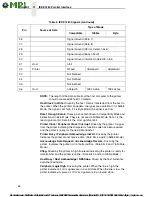
NOTE:
The length of the data cable from the host computer to the printer
should not exceed 32 feet (10 meters).
Host Clock / nWrite.
Driven by the host. Data is transferred from the host to
the printer. When the printer sends data, two types are available. If it is Nibble
Mode, the signal is set high. If it is Byte Mode, the signal is set low.
Data 1 through Data 8.
These pins are host-driven in Compatibility Mode and
bidirectional in Byte Mode. They are not used in Nibble Mode. Data 1 is the
least significant bit; Data 8 is the most significant bit.
Printer Clock / Peripheral Clock / Interrupt.
Driven by the printer. A signal
from the printer indicating the character or function code has been received
and the printer is ready for the next data transfer.
Printer Busy / Peripheral Acknowledge / nWait.
Driven by the printer.
Indicates the printer cannot receive data. (Data bits 4 and 8 in Nibble Mode.)
Acknowledge Data Request / nAcknowledge Reverse.
Driven by the
printer. Indicates the printer is in a fault condition. (Data bits 3 and 7 in Nibble
Mode.)
Xflag.
Driven by the printer. A high true level indicating the printer is ready for
data transfer and the printer is online. (Data bits 2 and 6 in Nibble Mode.)
Host Busy / Host Acknowledge / NDStrobe.
Driven by the host. Activates
auto-line feed mode.
Peripheral Logic High.
Driven by the printer. When the line is high, the
printer indicates all of its signals are in a valid state. When the line is low, the
printer indicates its power is off or its signals are in an invalid state.
26
Signal Ground (Data 7)
27
Signal Ground (Data 8)
28
Signal Ground (PError, Select, nAck)
29
Signal Ground (Busy, nFault)
30
Signal Ground (nAutoFd, nSelectIn, nInit)
31
Host
nInit
32
Printer
NFault
nDataAvail
aDataAvail
33
Not Defined
34
Not Defined
35
Not Defined
36
Host
nSelectIn
1284 Active
1284 Active
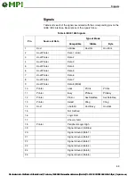
Table 6. IEEE 1284 Signals (continued)
Pin
Source of Data
Type of Mode
Compatible
Nibble
Byte


